-
1Building the Frame
![]()
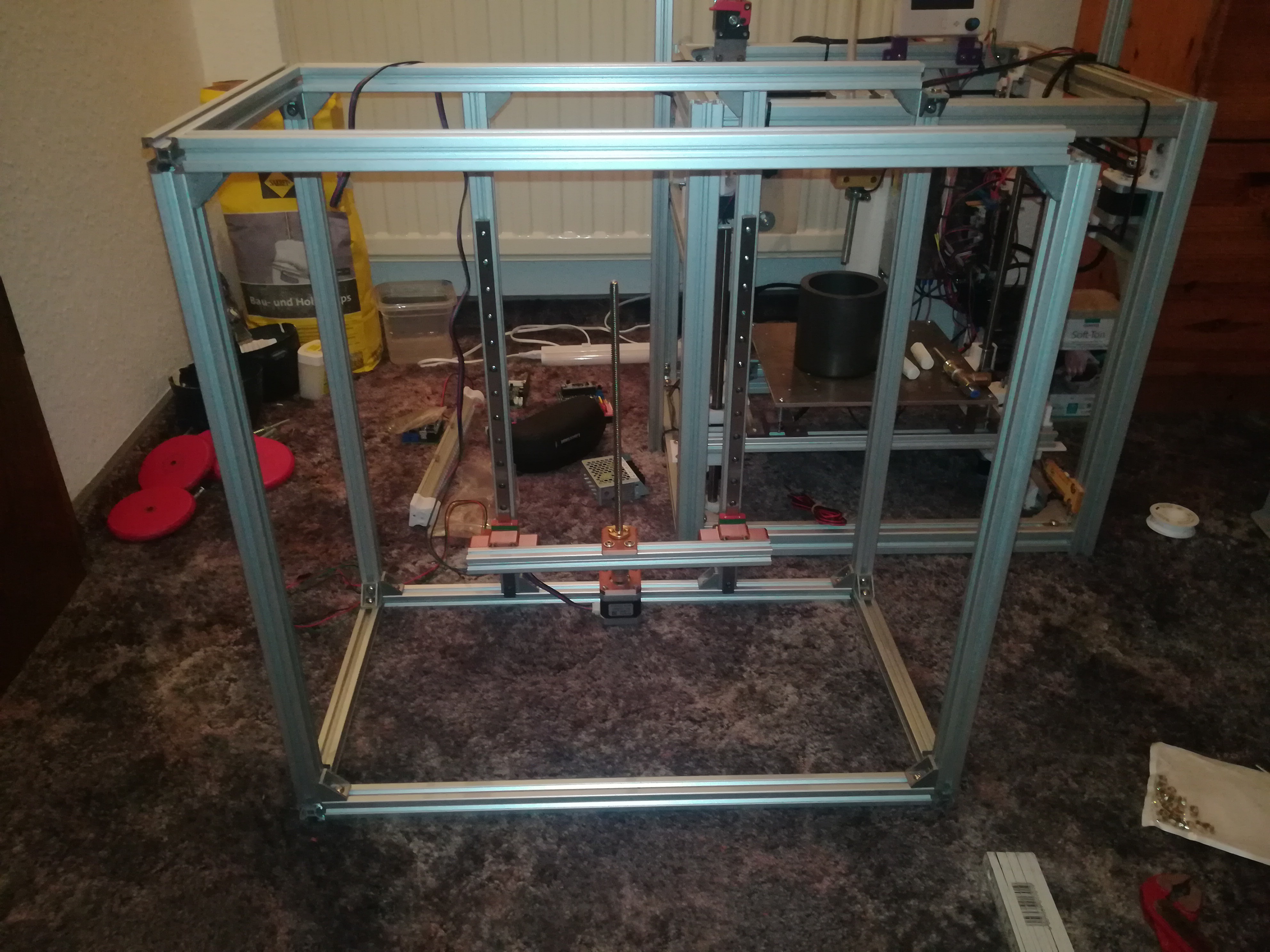
You can start by building the frame.
It is made of 10 pieces 500mm 2020 profiles and 4 pieces 300mm 2020 profiles.
To attach them to each other I used 2020 brackets, T-Slot nuts and M5*8 screws.
-
2The Z Axis
![]()
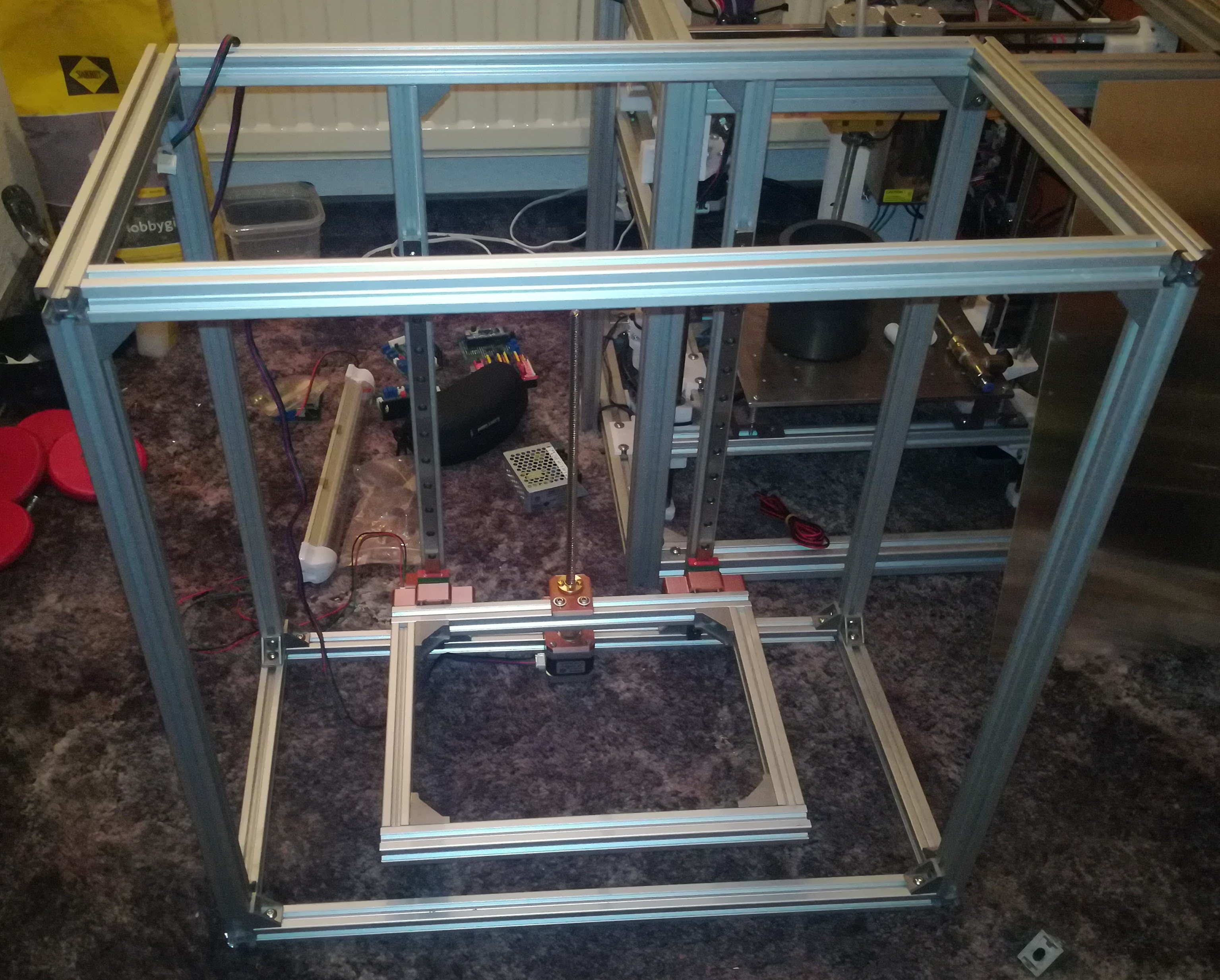
For the Z axis I used two sets MGN12H linear rails which I mounted to two of the 2020 profiles. For mounding them you need either the right slide blocks or you can 3D print the slide blocks, to mount them with M3 screws and nuts to the profiles.
For building the work area you need two 300mm and two 200mm 2020 profiles which you can attach to each other with corner brackets, M5*8 screws and T-Slot nuts like the frame.
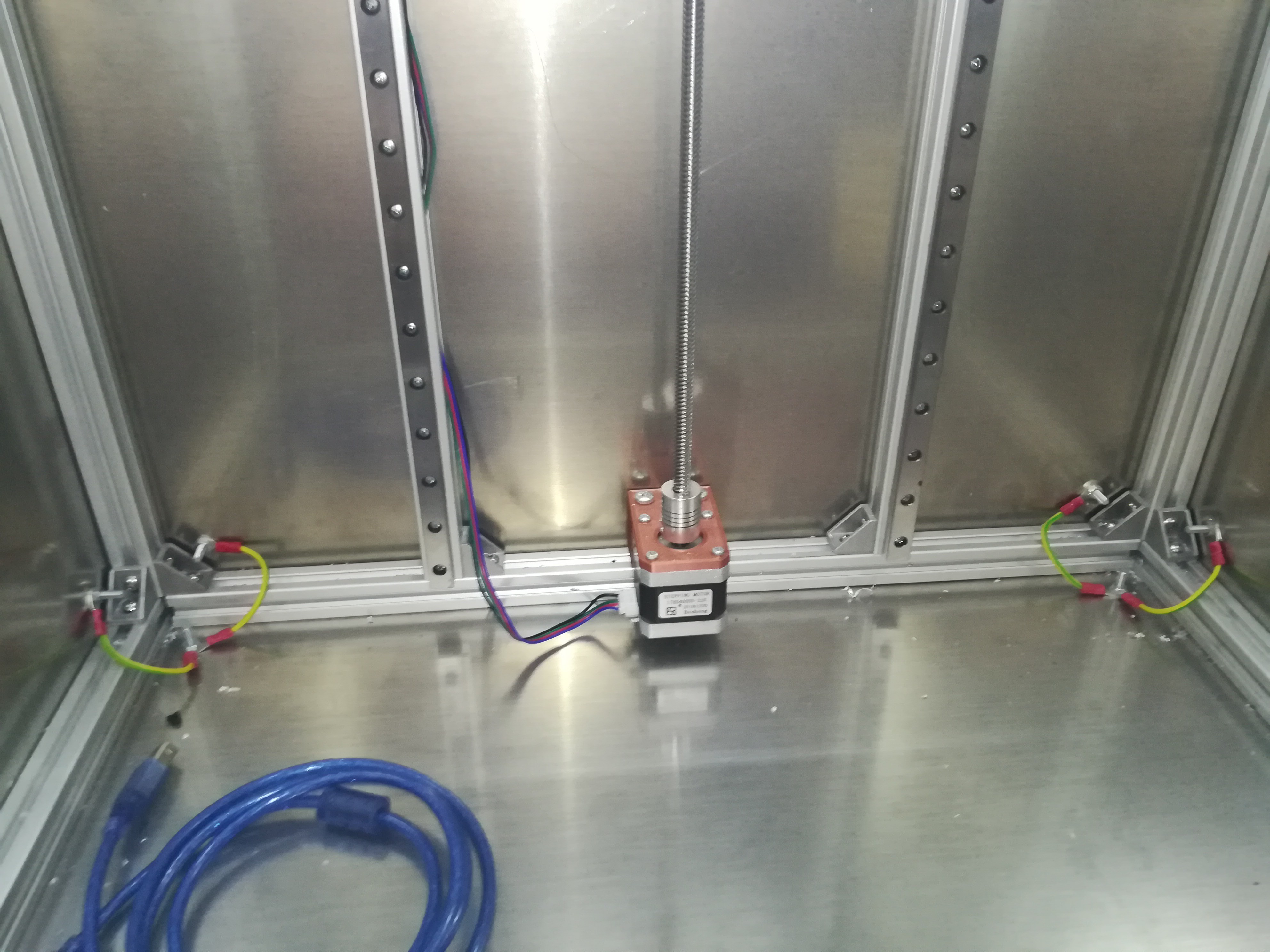
Next you can mount the Nema 17 stepper for the Z axis with the 3D printed part on the middle of the lower profile.
After that you can mount the 3D printed parts for the MGN12Hs on them.
Afterwards you can mount the T8 nut in its 3D printed part and attach them to the back of the work area.
Next you can mount the work area to the MGN12H 3D printed part with M5*10 screws and t-slot nuts.
Insert the T8 threaded rod into the motor coupler and mount both to the stepper motor. Place the work area with the T8 nut on top of the rod and you are almost done with the Z axis.
The last thing is the endstop.
Mount it on its 3D printed part and both to the left profile with the MGN12H.
-
3Adding the Plates
![]()
![]()
![]()
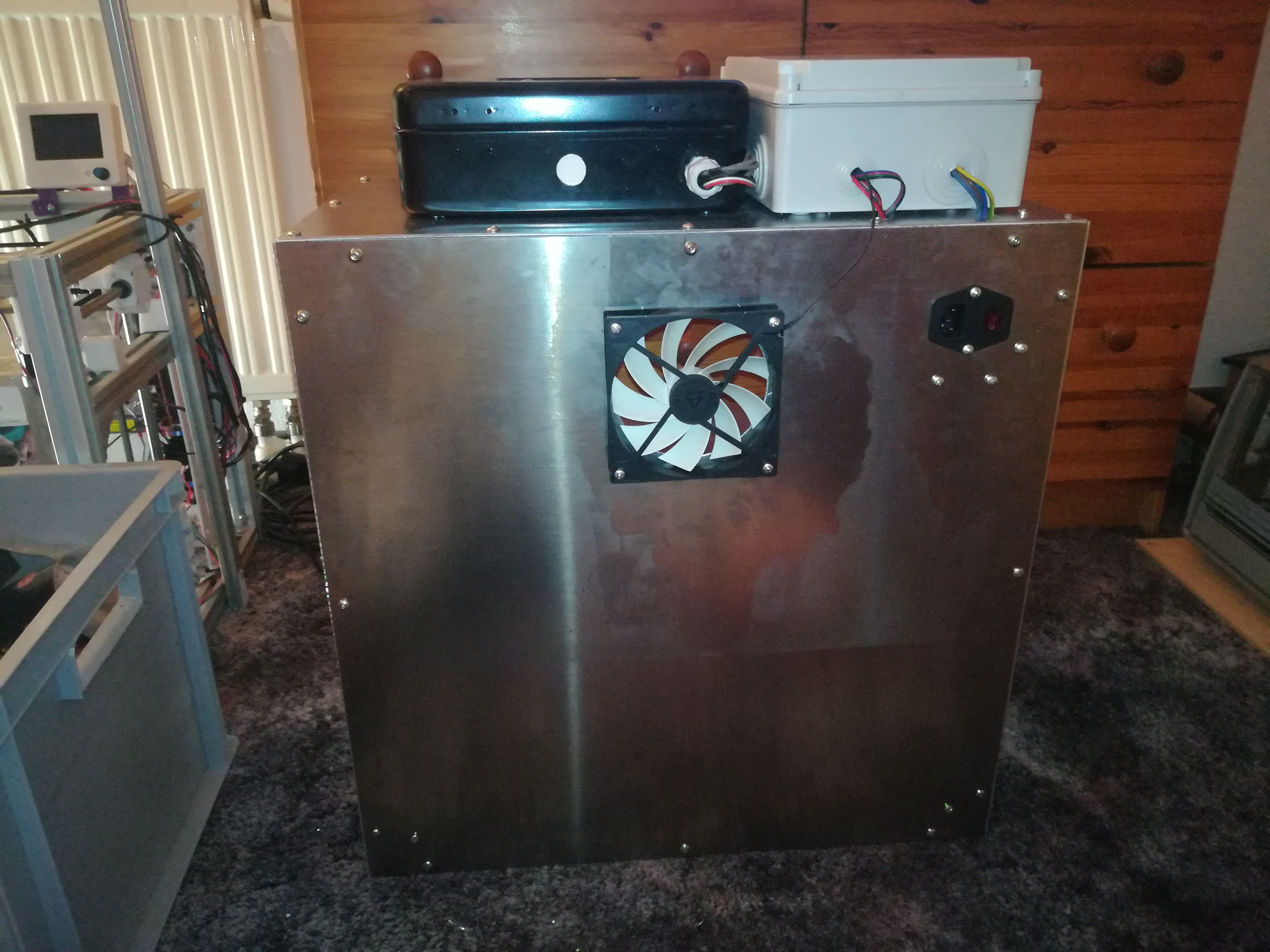
Add the 540*300*2mm plates to the top, bottem, left and right.
Drill holes in them to mount them with M5*8 screws.
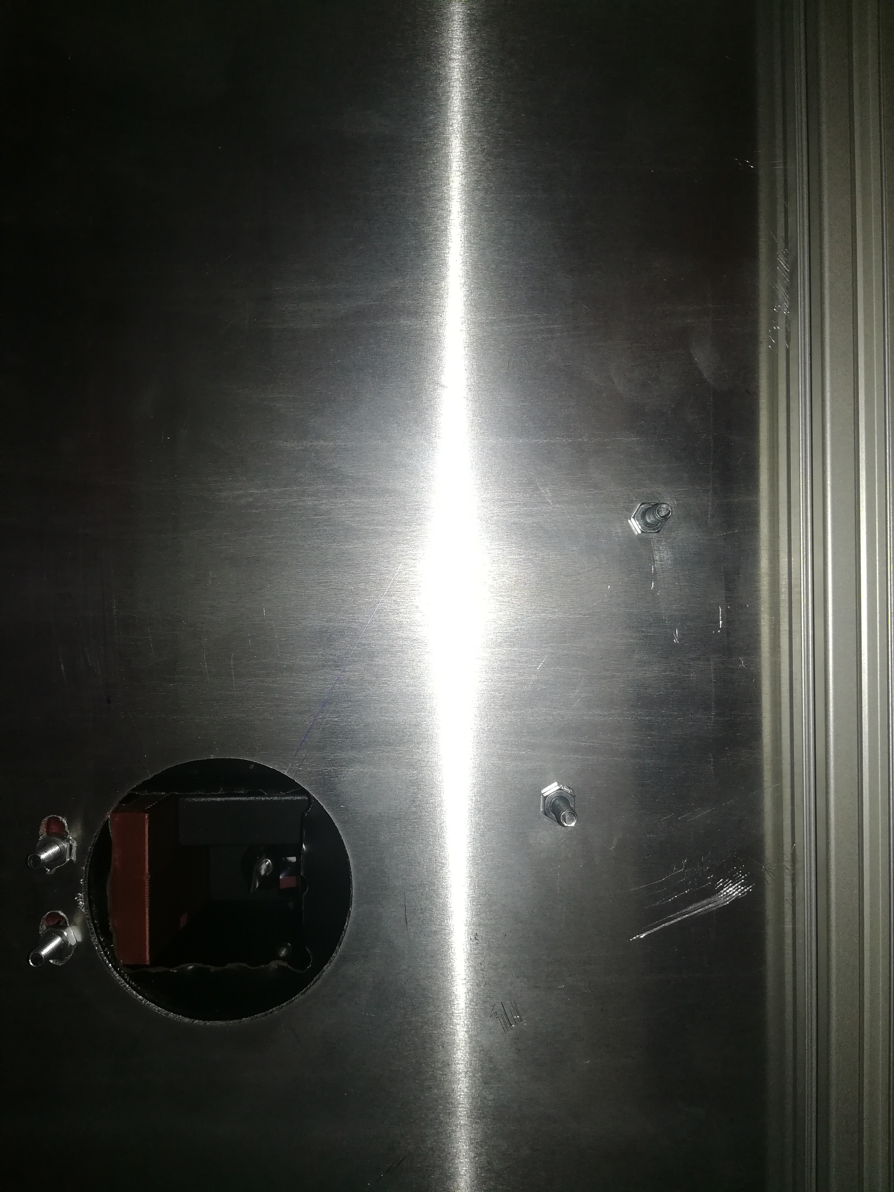
The one at the top needs a cutout for the laser in the middle and holes for cables to reach through.
Add the 300*220*2mm plate to the work area.
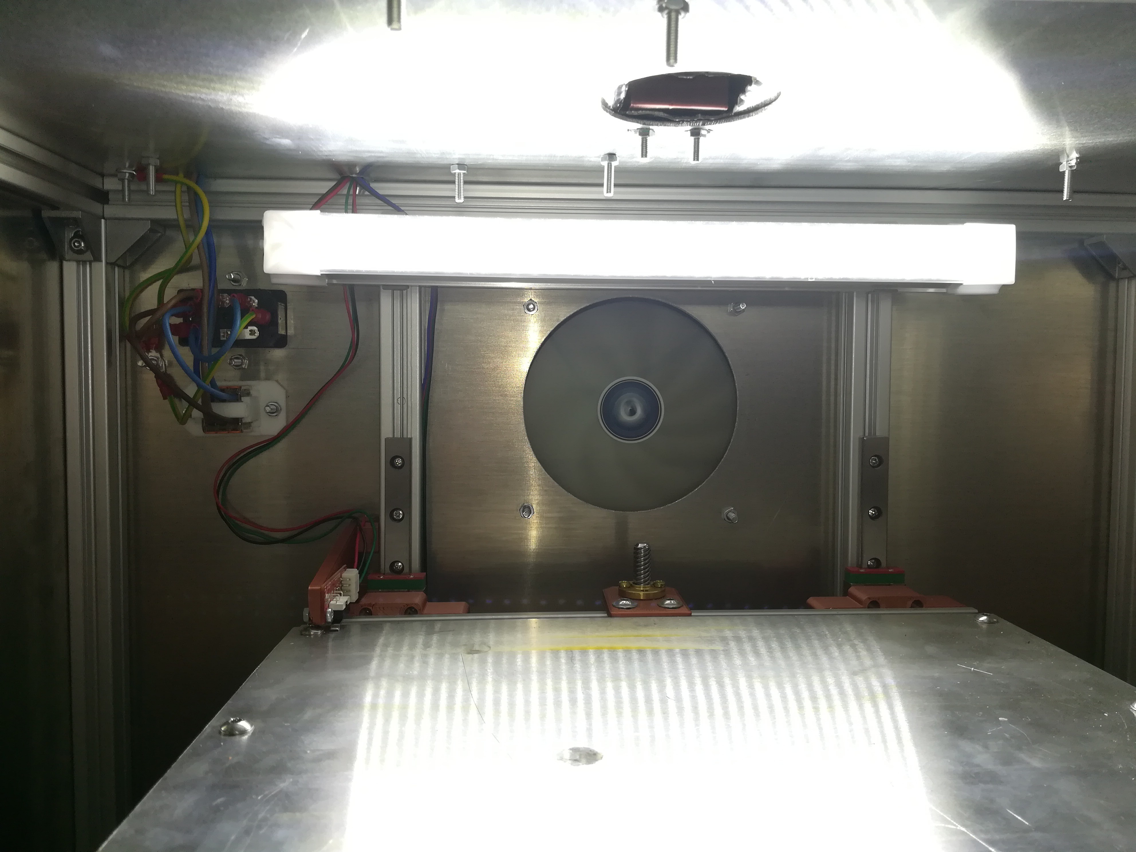
Last you can add the 540*540*2mm backplate which needs a cutout for the IEC socket and the 120mm fan. I cut them out with a plasma cutter cnc, but if you have none to hand you can cut them out by drilling holes along the outcut's outline and working them out with pliers and a file.
-
4Adding Electronics to the Frame
Warning: In this step you add the mains connection. Make sure you know what you are doing to not hurt or kill yourself.
![]()
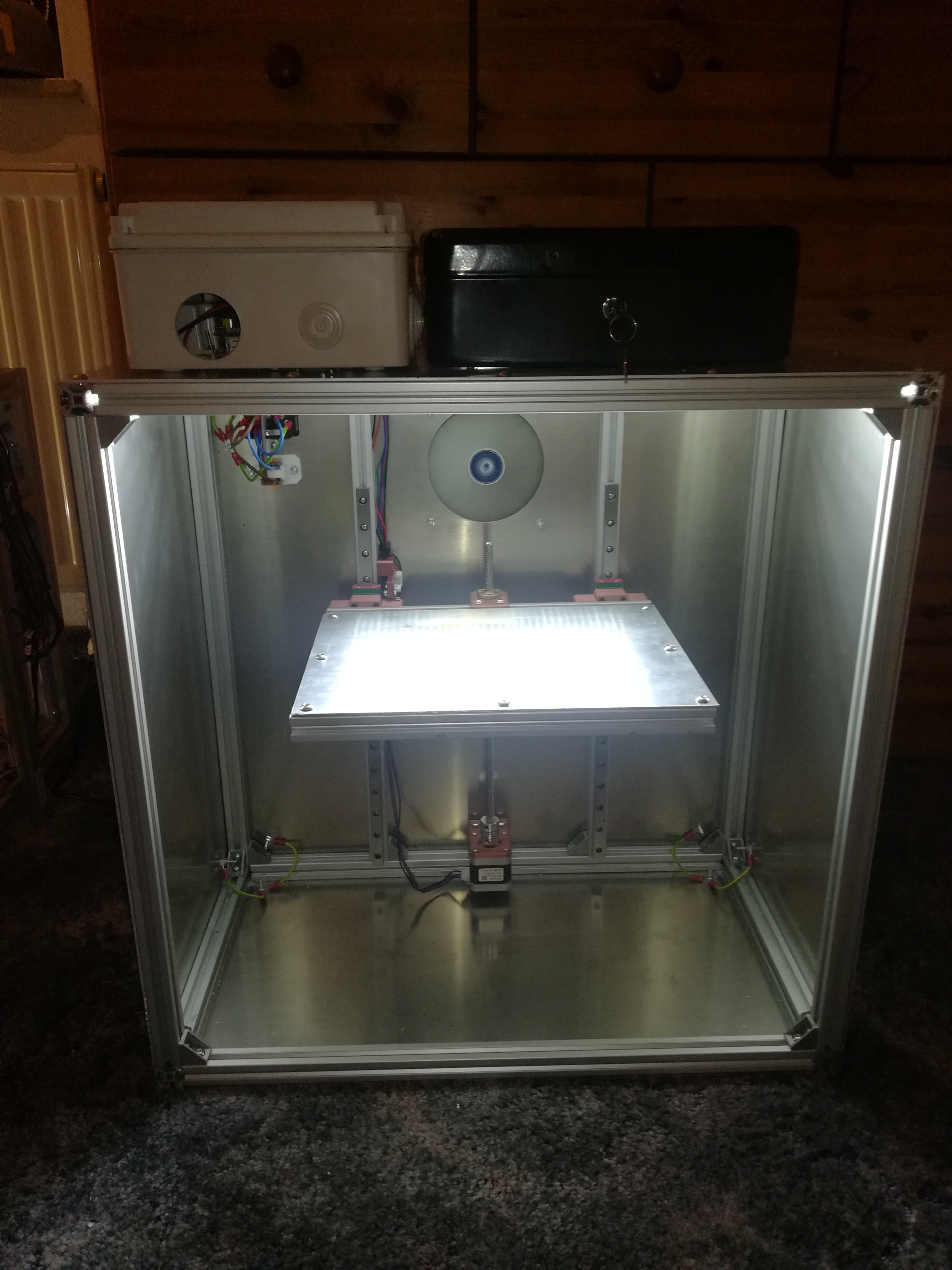
Mount the 120mm fan to the back with M4 screws and a lamp to the two profiles in the middle.
Add the stepper motor and endstop cable.
After that you can add the IEC socket to the backplate. To power the two PSUs you can add two WAGOs in their 3D printed parts to the backplate to distribute the connections.
![]()
You should also add the grounding and connect all touchable conductive surfaces together to keep everything safe.
The work on the machine body is now complete and there is only work on top of it to do.
-
5Electronics Box and Laser Box
![]()
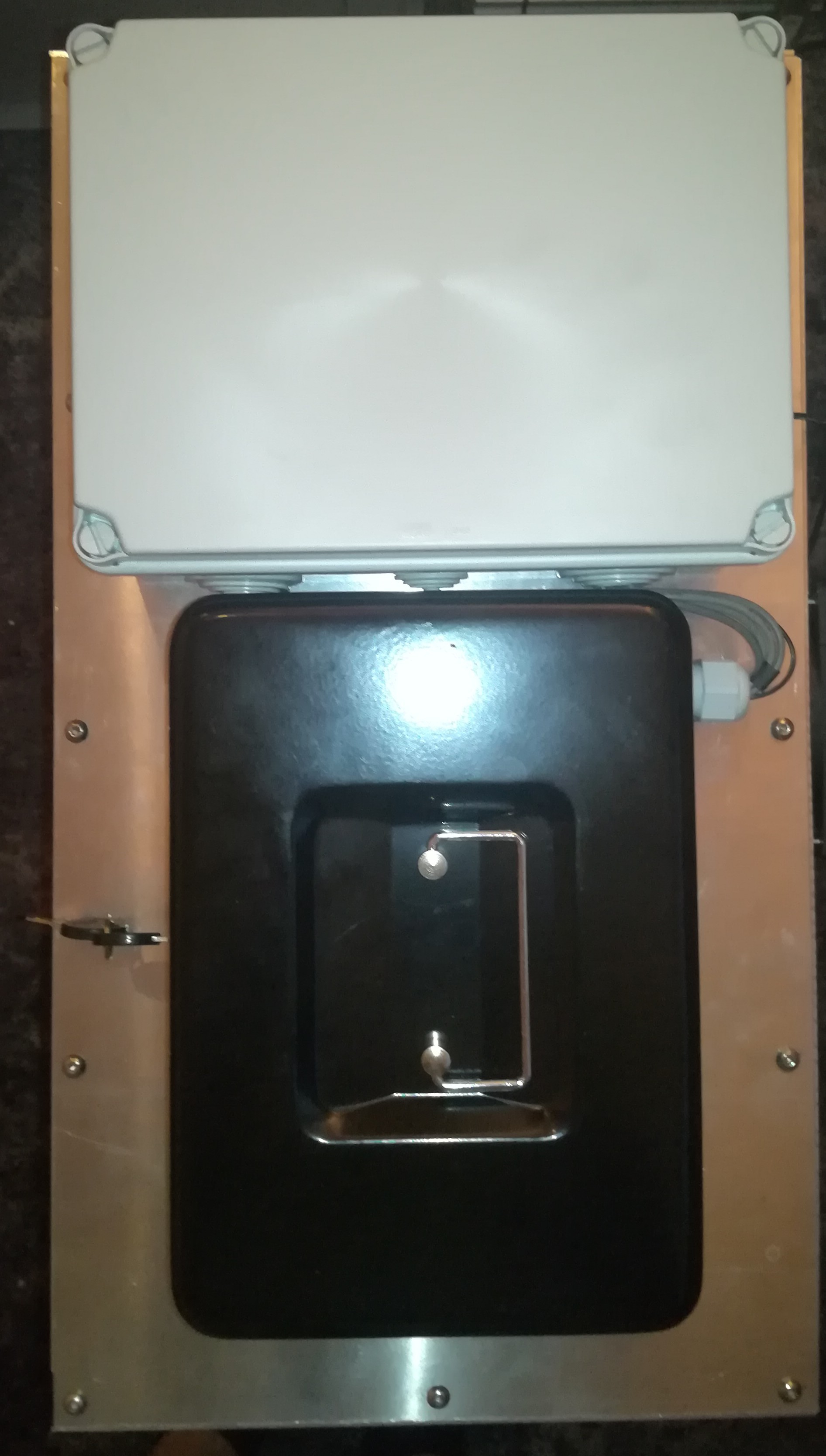
Next you can mount an electronics box and a box for the laser on top of the machine.
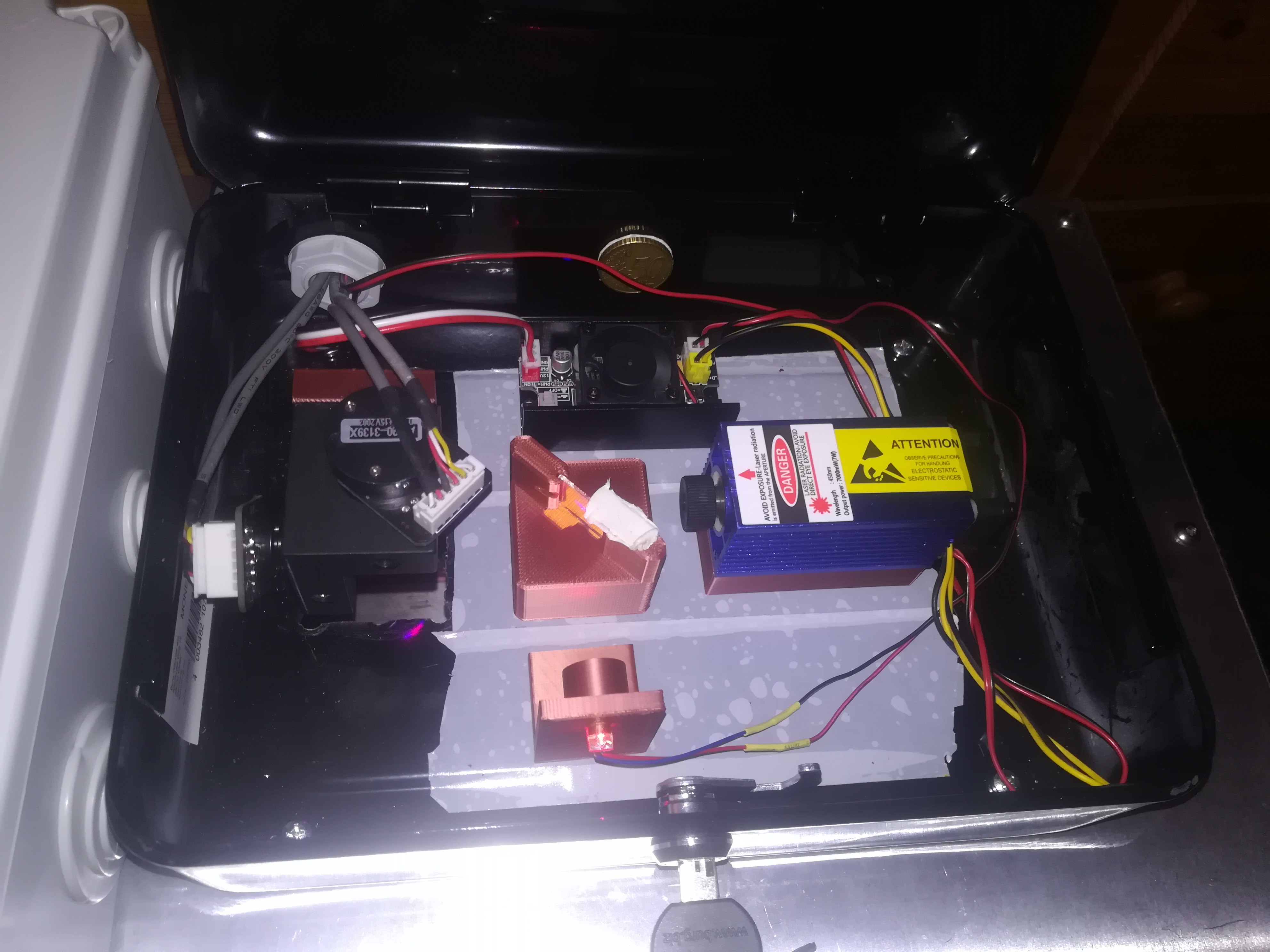
For the laser box I used a normal cash case because it is light tight and can not be set on fire by the laser.
Further, if you have to work on the laser you can just open the lid without unscrewing any screws.
![]()
Inside the box: Galvo assembly + 3D printed part, red dot laser + 3D printed part, laser driver, laser + 3D printed part, dichroic mirror + 3D printed part.
You can start by cutting a hole underneath the later galvo position - on the left of the box but far enough from the border, so that there is space to adjust the galvos with the cables plugged in.
You can then add the 3D printed parts to the box. Mount the galvo bracket with two M4 screws. I placed the other parts on a layer of double sided tape, but if you want you can mount them more permamently in position after adjustment.
Mount the case on the top with the galvos above the hole in the middle of the top plate and you are done for now.
Also mount a big enough electronics box onto the top next to the laser box.
-
6Building the Converter Boards
![]()
![]()
![]()
![]()
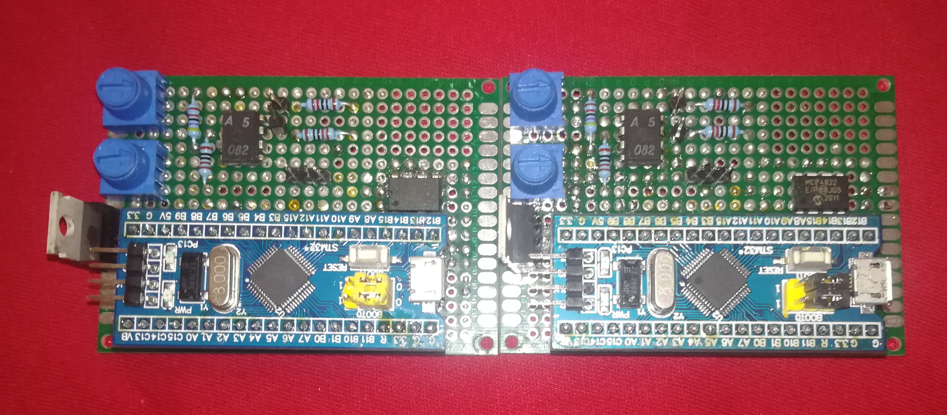
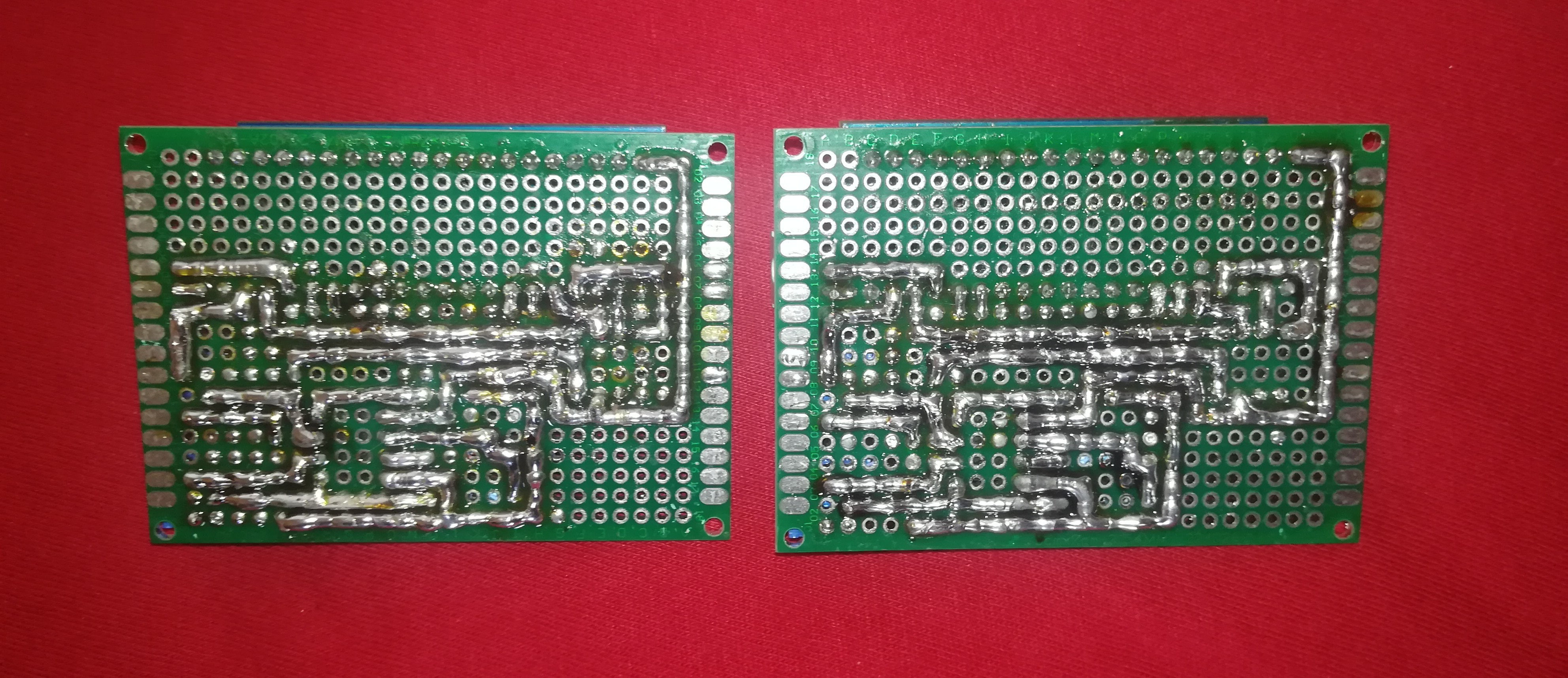
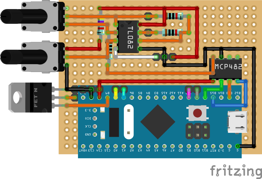
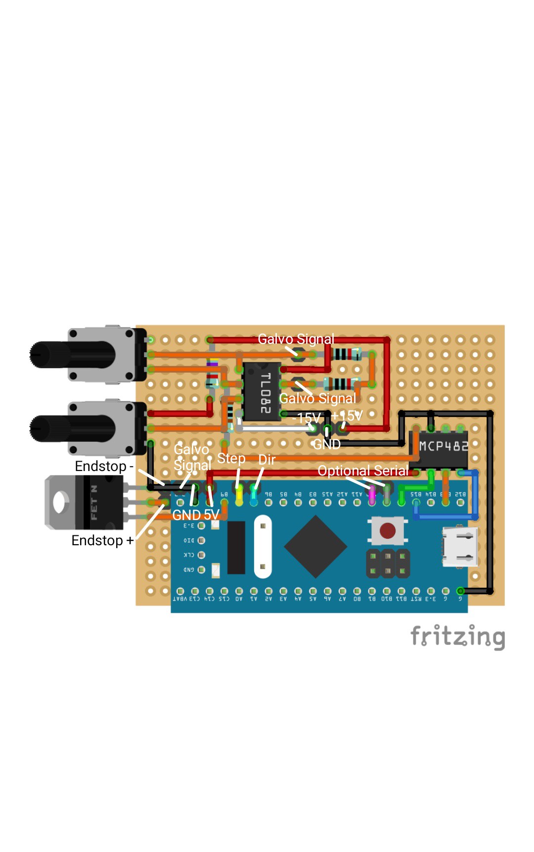
Next you can build the two identical converter boards.
The parts needed for them are:
-STM32 "Bluepill" Board
- Perfboard 24*18 holes
- 2x 10k potentiometer
- IRFZ44N MOSFET
- MCP4822 DAC
-TL082 opamp
- 1x 1k resistor
- 2x 10k resistor
- 1x 47k resistor
- some header pins
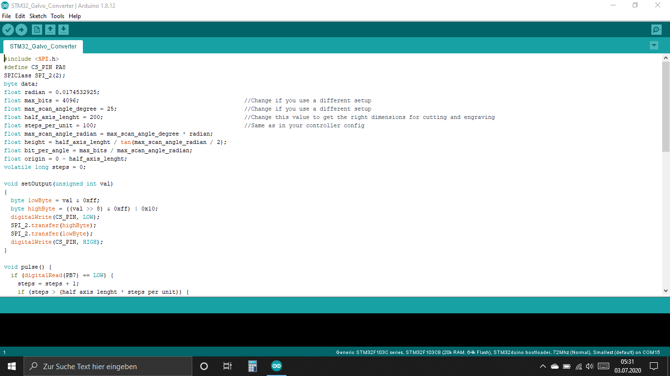
Solder them together like on the pictures and upload the .ino file to them.
-
7Electronics
![]()
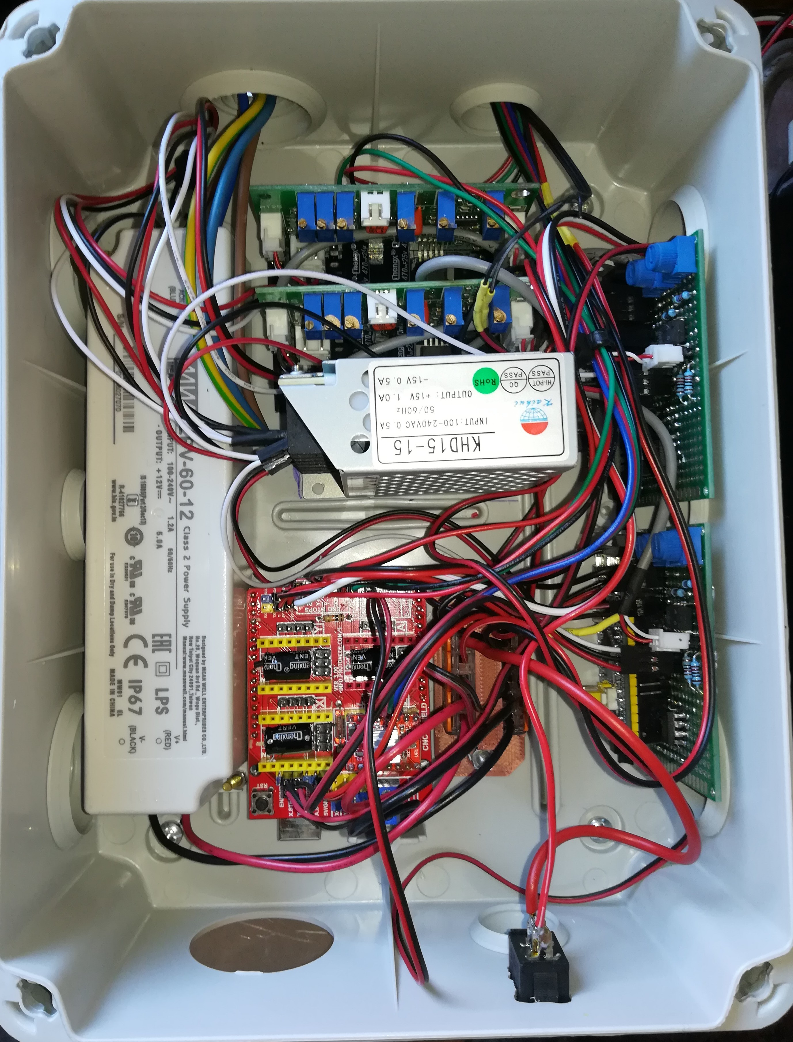
Here is a picture of my electronics box. The parts inside are:
A 12V 5A PSU, a switch for the laser, two WAGOs with 3D printed part, Arduino UNO + CNC Shield, Galvo PSU, two galvo drivers and two converter boards.
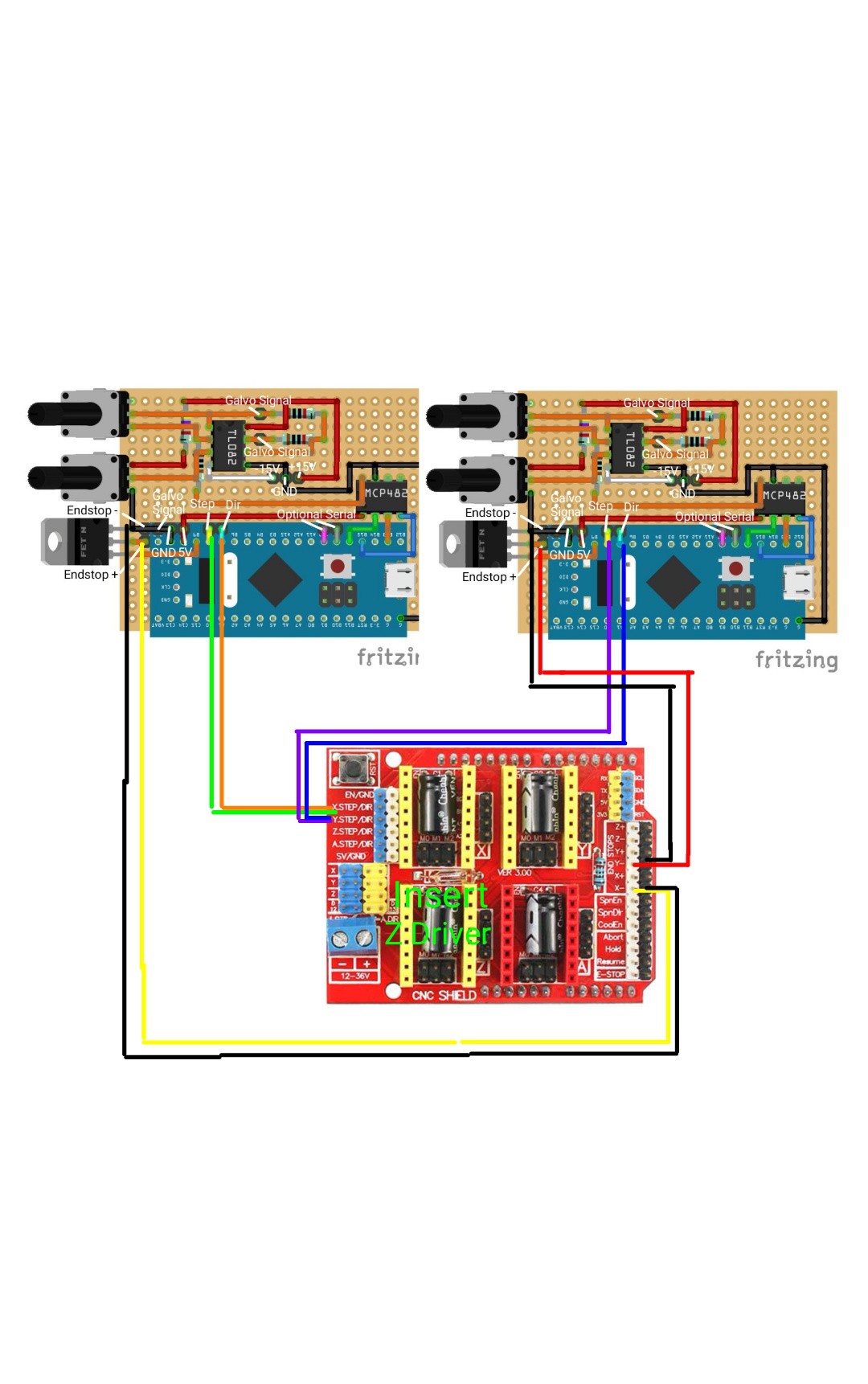
The wiring should be really straightforward.
Connect the both PSUs to the mains voltage. Connect the 12V PSU to the WAGOs and to it the laser (switch between +12V), the LED lamp, the fan and the CNC shield. Connect the galvo PSU's +15V GND -15V to the two galvo driver and two galvo converter boards.
Connect the galvo driver to the galvos and the galvo converter boards. Place the ±5V galvo signal connector on the two pins next to each other and the GND pin on the lower left (no space for GND between the two other pins).
Connect the endstop for Xmin to the X converter board and the endstop for Ymin to the Y converter board.
Same with step and dir. X to X and Y to Y.
Power both converter boards from the CNC shields 5V connection.
Power the Z endstop from the CNC shields 3.3V connection and wire it to Z min.
Add a stepper driver and wire the stepper motor to Z.
Wire the cutting laser to the PWM output and the red dot laser to the coolant output.
This should be the whole wiring - If I have forgotten something let me know :)
To test everything you can install grbl on the arduino and test with your favorite laser software eg. lasergrbl, laserweb or lightburn whether everything works as it should.
![]()
-
8Laser Alignement
Warning:
Before turning the laser on for the first time make sure you have the right safety glasses to protect your eyes.
![]()
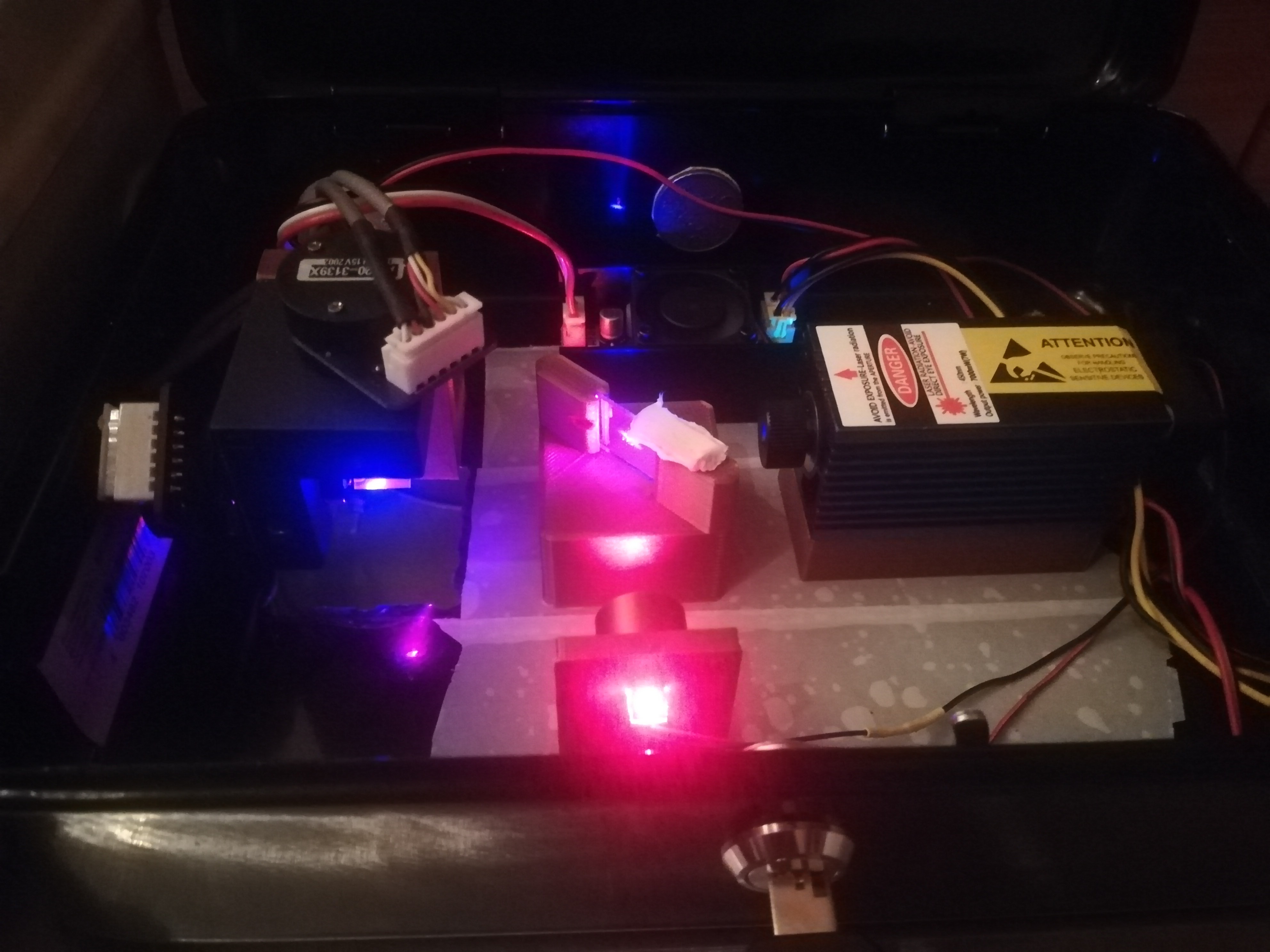
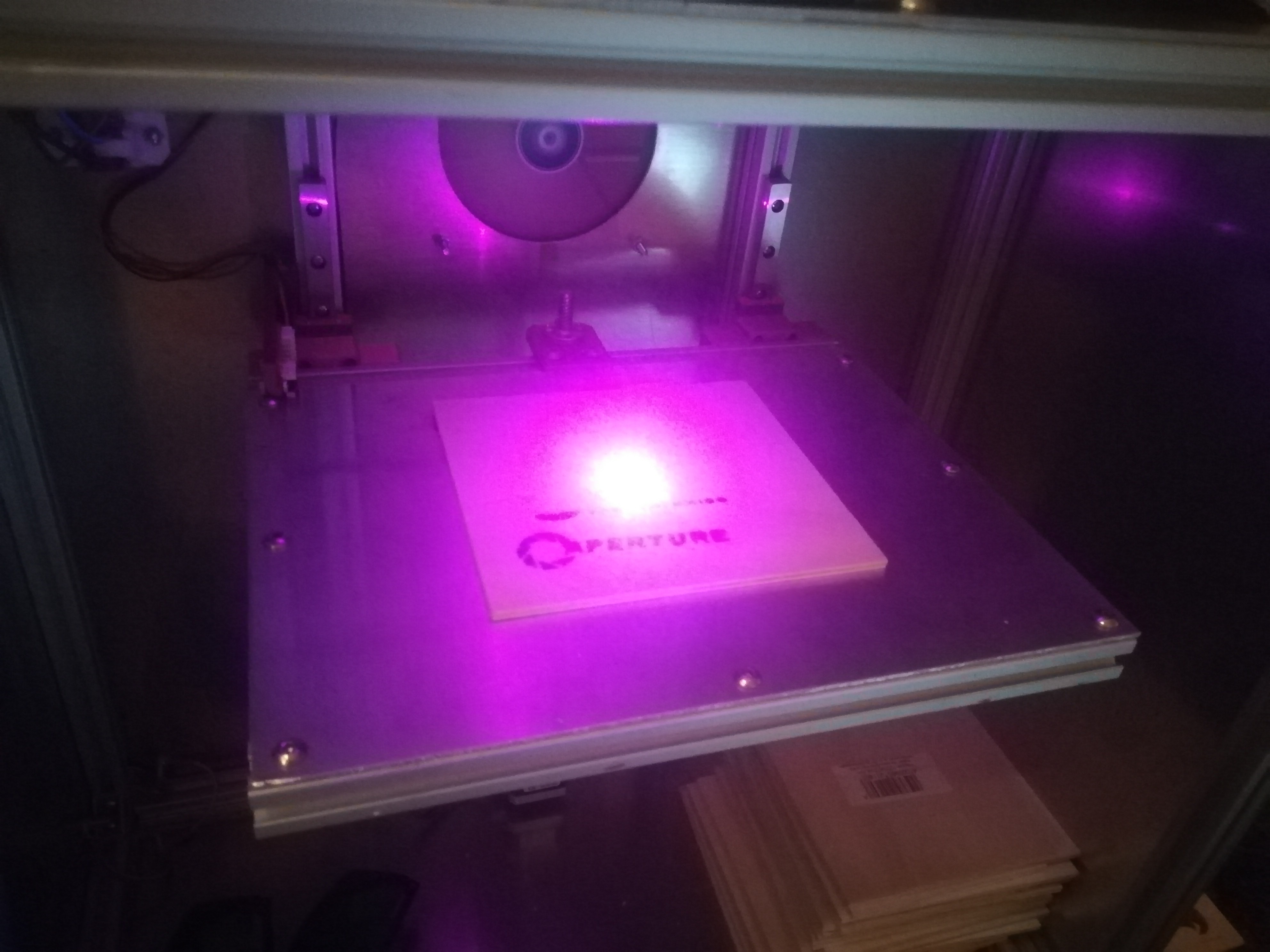
For aligning the laser you have to turn on the red laser and the cutting laser with the lowest possible power setting.
Put something like plywood on the work area, home all axis and align the galvos so that they reflect the laser straight on the work area.
Put the dichroic mirror between the galvo and the cutting laser and make sure that it is angled about 45° to reflect the red laser.
![]()
Adjust the focus of the blue laser and try to align the red and blue laser dots as good as possible and you are done.
-
9Machine Alignment
(Copied from a buildlog)
To get the cutted and engraved pattern to match the desired dimensions, the machine needs some alignment.
I started with aligning the galvos in the galvo assembly.
On the Z axis as well as on the both Step/Dir to Galvo Converters there is an endstop for repeatable positioning.
For aligning them I first homed everything and moved the galvos in the center of the axis. Then I aligned the two galvos in the assemby with the laser on lowest power, so that the laser dot hits exactly vertical the center of the machine. Then I tightened the screws of the galvo assembly, to hold them in place.
Next I mounted the Z endstop on a fixed position - the best distance would be the least distance needed to use the whole area and have enough clearance to drive the Z axis down for thicker workpieces. You can test it by moving the galvos with the laser at lowest power via your laser software to see how far they can move.
After that I did test cuts and measured them to see whether the dimensions are right and changed the half_axis_length on both converters until the dimensions were as they should be.
-
10Working with the Galvo Laser
Using the machine should also be really straightforward.
-Put your safety glasses on
-Open a window
-Turn the machine on with the laser switched off
-Connecting the Arduino to a PC and wait for it to boot up.
-Switching the laser on
-Start your favorite laser software.
-Placing the workpiece under the endstop
-Homing the machine
-Turn the red dot laser on with M8
-Find your origin position
-Run your laser job
-Enjoy :)
Hope these instructions can help you building this machine or using parts of it for your own project.
If you have any questions let me know :)
 Dominik Meffert
Discussions
Become a Hackaday.io Member
Create an account to leave a comment. Already have an account? Log In.