 UTSOURCE
In this article, we will discuss how we can run a high voltage motor using IRF840 and 2N3055 with the 555 PWM and we will discuss the various circuit security measurements also for performing this operation.
First, we will discuss the IRF840 that what is the specifications and the use of this component
Introduction to IRF840
It is an N-Channel MOSFET that can be used in high power applications like this driving power to the motor.
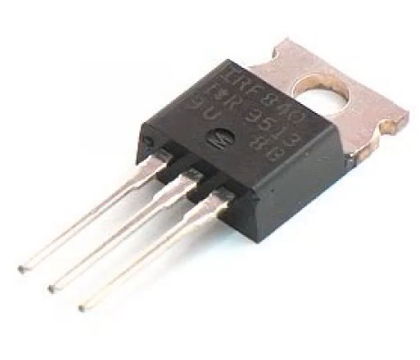
The above picture shows the physical description of an IRF840 module.
Specifications of IRF840
- This device shows a Dynamic dV/dt rating
- This device also shows a Repetitive avalanche rated
- Fast switching can be performed using this device.
- Ease of paralleling can be achieved by this device.
- Simple drive requirements can be also performed by this device.
Third generation Power MOSFETs provide the designer with the best combination of fast switching which is a unique feature, ruggedized device design is also another feature, low on-resistance and cost-effectiveness is the key element for using it in the circuit operations. The TO-220AB package is universally preferred for all commercial-industrial applications and also for the DIY Projects at power dissipation levels to approximately 50 W. The low thermal resistance and also the low package cost of the TO-220AB contribute to its wide acceptance throughout the industry. And over the personal projects.
Introduction to 2N3055
This is a 15 Ampere power transistor that is complementary to the silicon 60 Volts and 115 Watts.

Specifications of the Transistor 2N3055
The various specifications of the Transistor 2N3055 are given below which is an NPN Transistor
- The DC Current Gain is − hFE = 20 −70 for this transistor
- The collector current is IC = 4 Adc
- Collector−Emitter Saturation Voltage −VCE(sat) = 1.1 Vdc (Max) which gives it a safer zone of operation.
- Excellent Safe Operating Area is another key feature for this Transistor
- Pb−Free Packages are Available for this device which is another key security for circuit hazards.
The above picture gives a physical description of the Transistor 2N3055
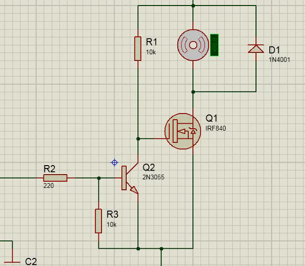
The complete circuit in simulation software

By triggering the PUSH button the speed of the motor can be controlled.
Basically, by pushing the button the speed of the motor can be decreased and this occurs because of the saturation point changes in the semiconductor materials.
The above experiment can also be done with 555 IC with the astable mode and by varying the frequency with the 5K POT the same phenomenon can be achieved.
Now look in the below circuit carefully there is a potentiometer inserted for the PWM speed control mechanisms.
Now you can vary the speeds of the motor by varying the potentiometer.
So we have performed a simulation successfully now you can try this same experiment by the use of various others POTs and various other ICs.
Conclusion
So we have discussed the various components that can be used in various circuit applications so for buying them at Best price please visit at utsource.net


 Mrinnovative
 Osman Mazinov
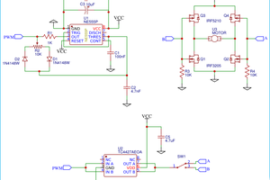
Good grief talk about overkill, why do you need a 2N3055 rated for 15A to drive the MOS transistor when the current through the 3055 can't be more than a few mA with that 10k pull-up resistor!