 kutluhan_aktar
To get notified when the set reading time is over, I utilized a Serial MP3 Player Module (OPEN-SMART) with Speaker, including my two favorite cartoon soundtracks as the playlist. Lastly, to develop an interface (menu) to control the mentioned modules and implement special features, I used an Arduino Nano and a Nokia 5110 Screen. You can get the more detailed information regarding the specialties of this device in Features.
As a prototype, I tried my code with the mentioned modules and Arduino Nano on two breadboards, as depicted in the figure below. The prototype was working properly, but it had redundant wirings that hinder me from using the device attached to my bookcase as I intended. Therefore, I decided to design a PCB to complete my project, including buttons to control the interface, headers to connect the modules, and embedded-resistors.

SeeedStudio sponsored my PCB design for this project with its fast and high-quality PCB / PCBA service. You can find more detailed information about the PCB and its fabrication process in Designing the RFID Reading Time Checker PCB.
Preview: What You Will Learn
- How to design a PCB
- How to use an MFRC522 RFID module with Arduino Nano
- How to register a new RFID card or tag UID to the EEPROM
- How to use a DS3231 RTC module with Arduino Nano
- How to use a Nokia 5110 Screen with Arduino Nano
- How to control a Serial MP3 Player Module (OPEN-SMART) with Speaker by using UART commands with Arduino Nano
- How to program an interface and a timer in Arduino
Features
When you open the device (RFID Reading Time Checker with MP3 Player and RTC), you should see the "Initializing..." message while it is checking the modules.

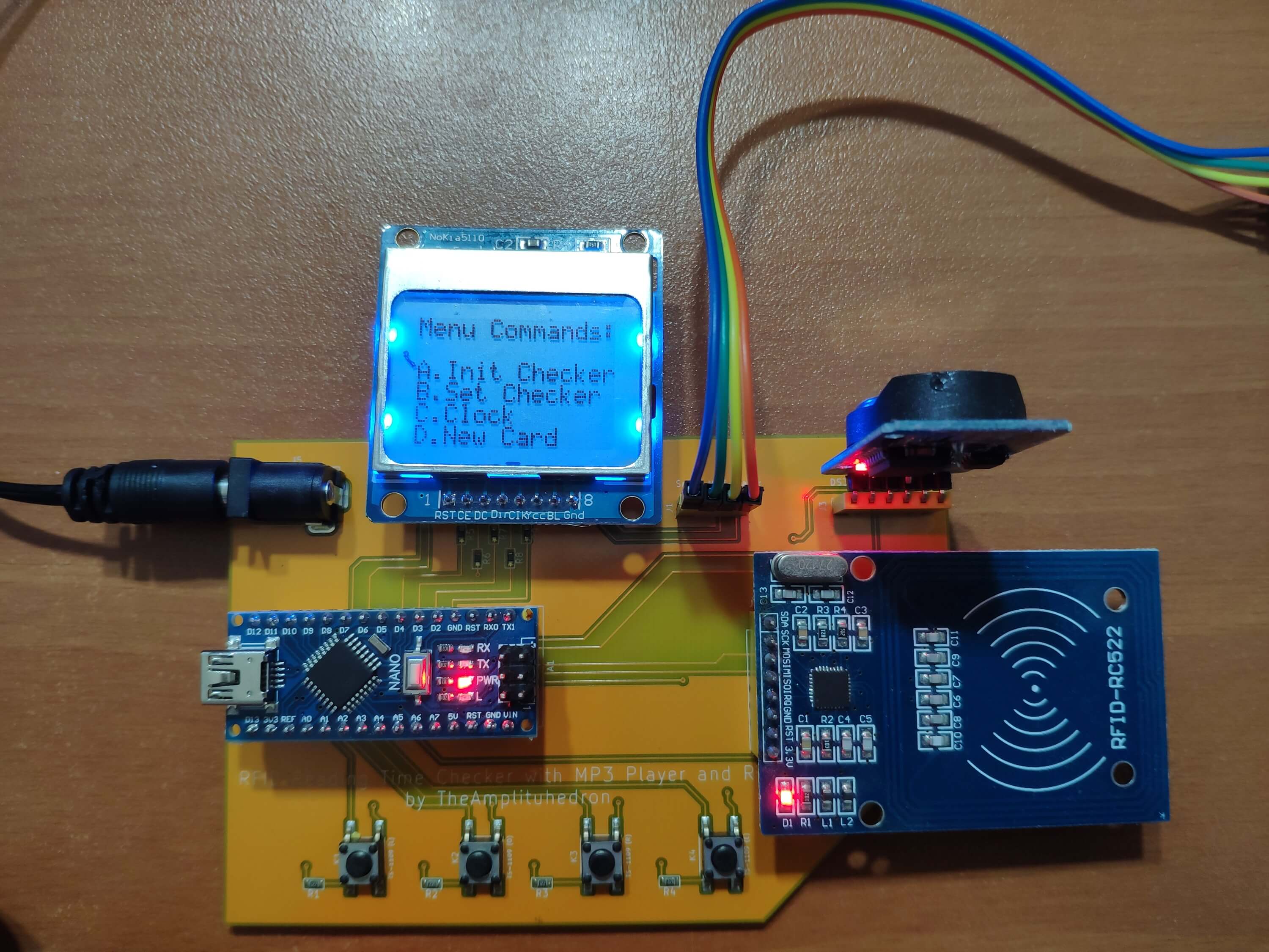
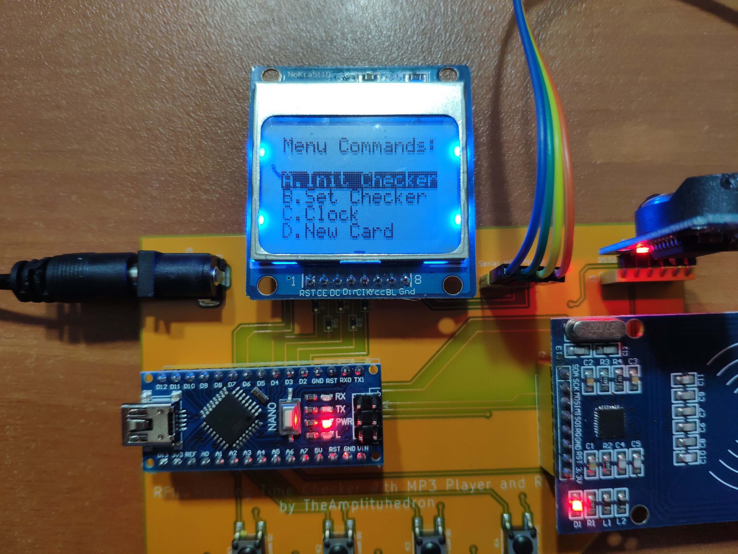
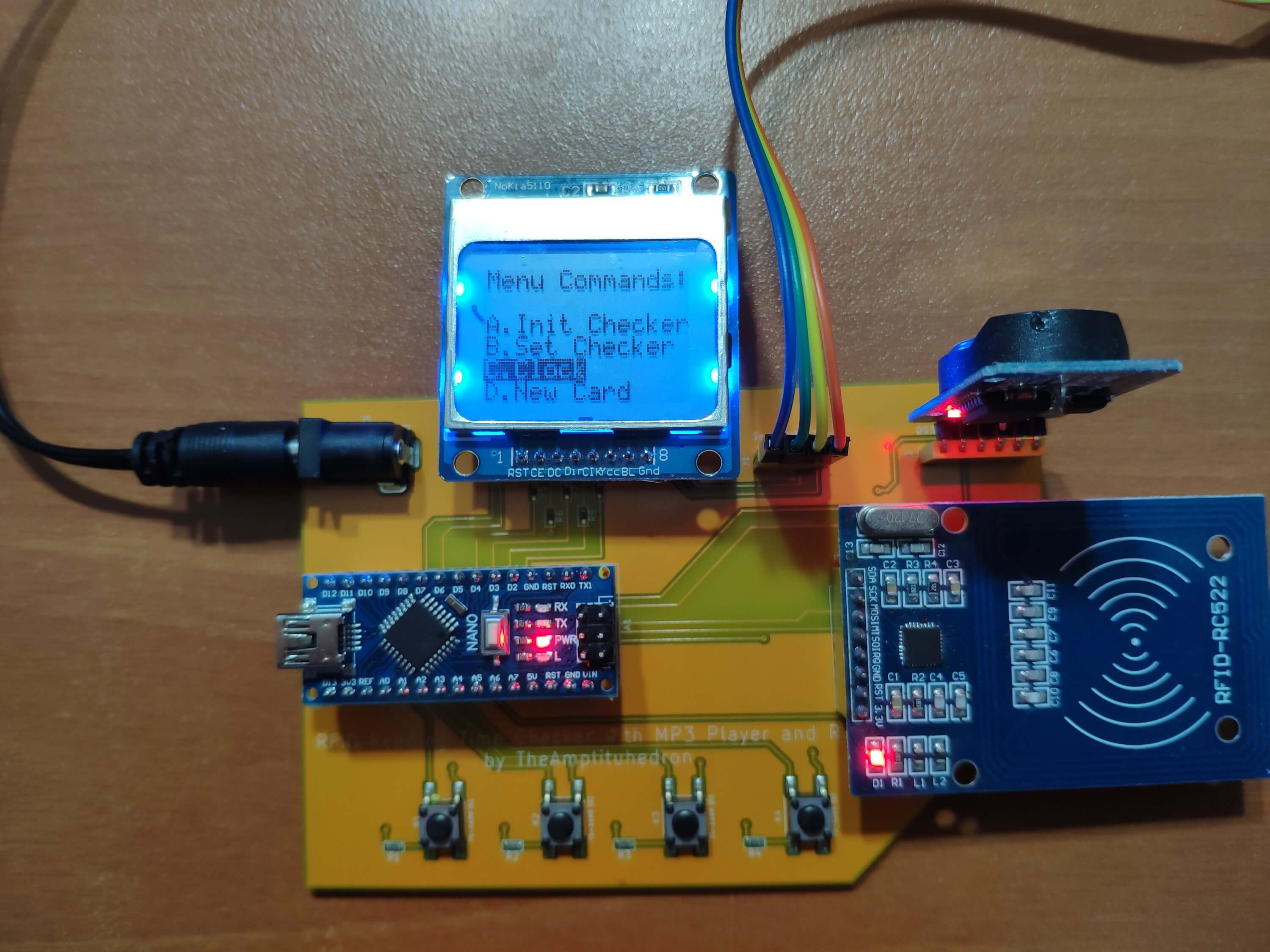
Then, the device will show you the home screen (interface), including four menu commands - A. Init Checker, B. Set Checker, C. Clock, and D. New Card. Each menu command lets you activate a different feature of the device.
To select and activate menu commands, you need to use the buttons on the PCB, as explained below, named Left, OK, Right, and Exit (from left to right).
Press Right to go down and Left to go up.
To select a menu command, press OK.
To return to the home screen after selecting, press Exit.
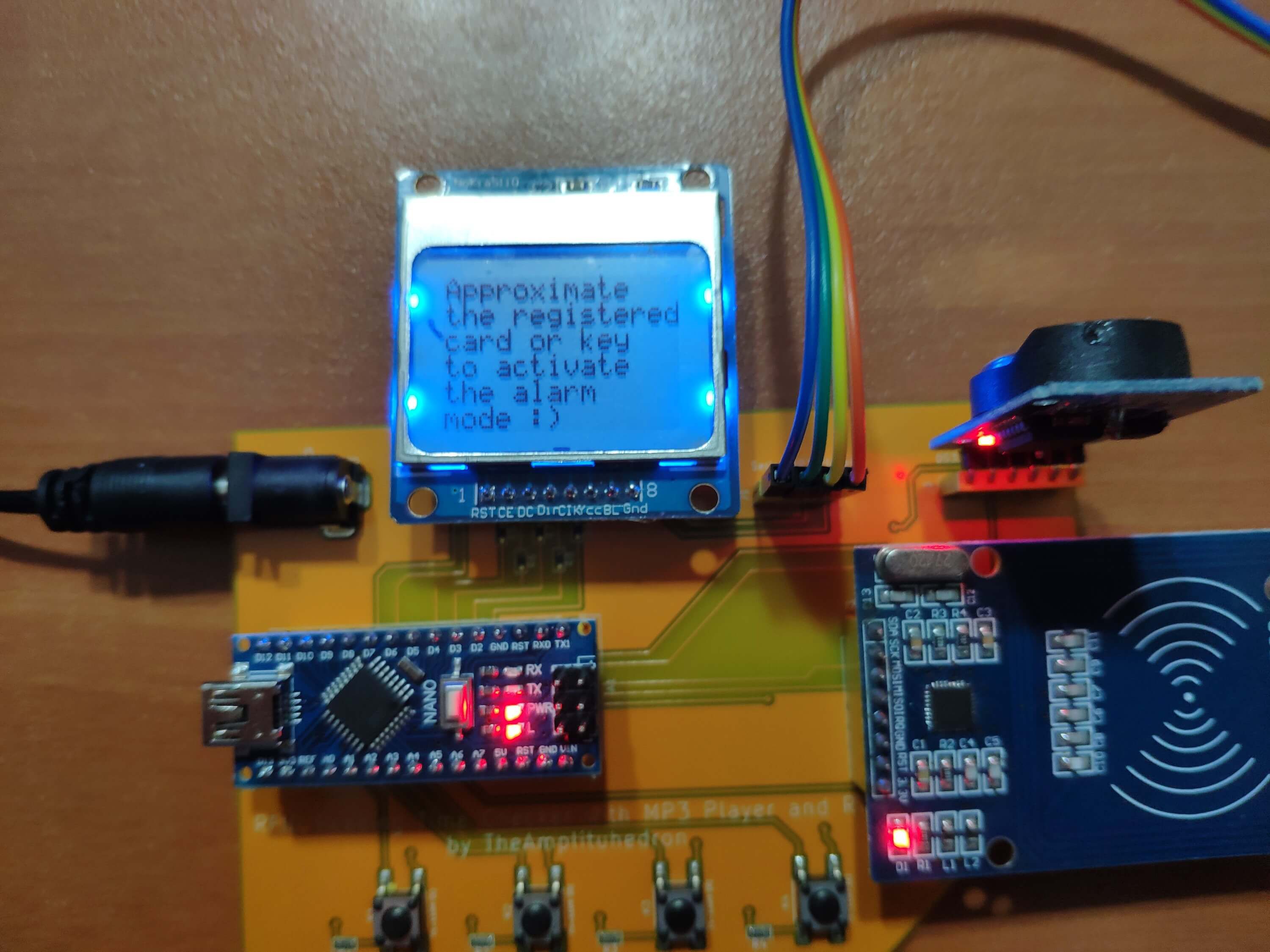
A. Init Checker
Approximate the registered RFID card or tag in the EEPROM to the MFRC522 RFID module to activate the alarm mode. The device displays the clock icon if the alarm mode is activated.
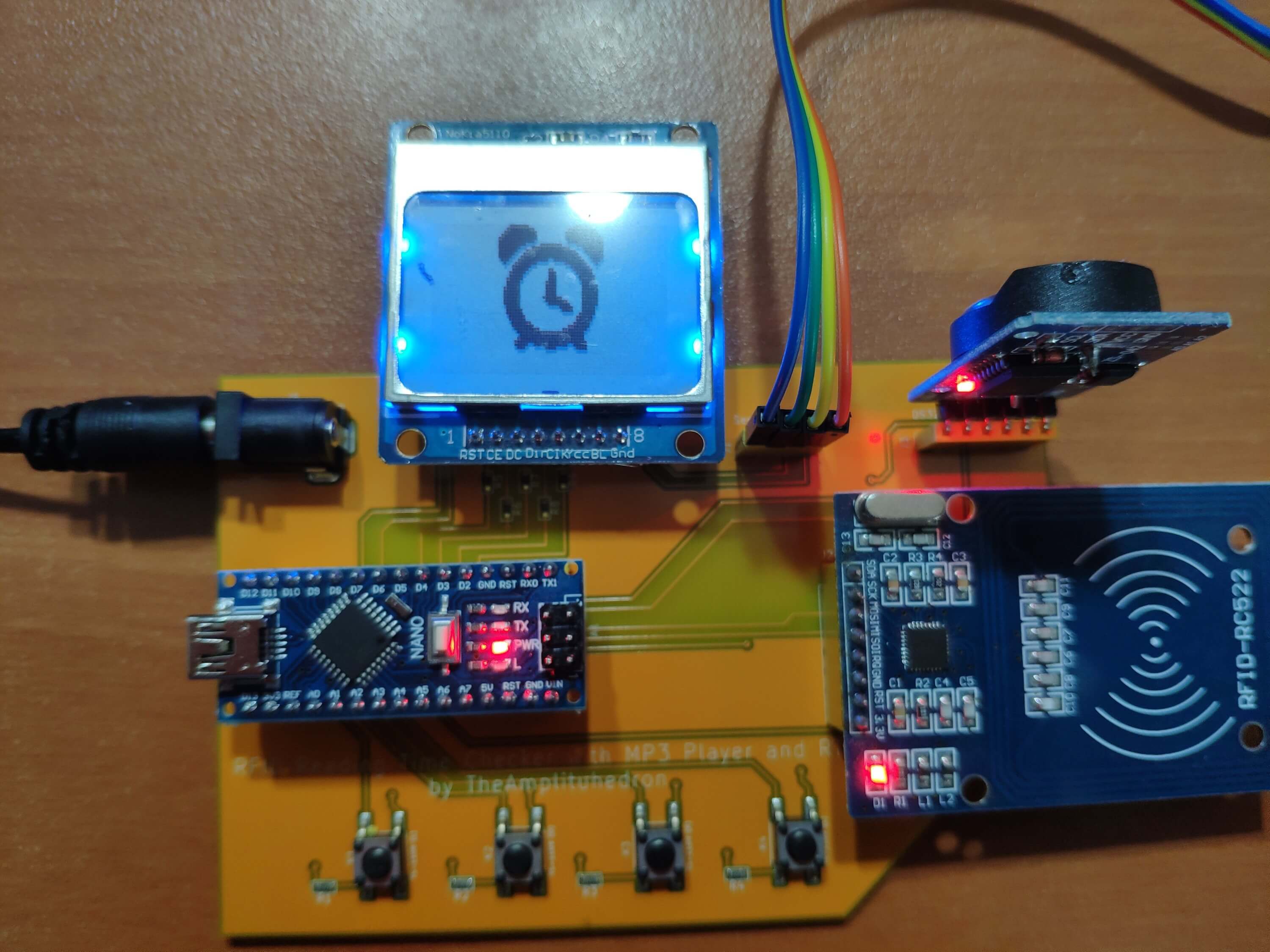
In the alarm mode, the device notifies you when the timer (RTC) has reached the set reading time - for instance, 15:21 - by displaying the Spider-Man icon and playing the second song (Spider-Man Cartoon Theme Song) in the playlist of the Serial MP3 Player (OPEN-SMART).
In other words, as its name implies, the alarm mode is an alarm that is activated by the registered RFID card or tag and rings when set (the reading time). So, depending on your routine, you can check your reading time daily.
To return to the home screen, press Exit.


Important: In the alarm mode, you can play songs without waiting for the device to notify you with the second song and the icon if you want to listen to the playlist:
Press Right to play the first song in the playlist.
Press Left to pause the playing song.
Press OK to play (continue) the playing song.
B. Set Checker
Set the reading time - for instance, 14:2 - to get notified when the timer (RTC) has reached the reading time if the alarm mode is activated. When the reading time is set, it is saved by the device until further changes.
Press Right to increment minutes by 1.
Press Left to decrement minutes by 1.
If minutes exceed 59, the device increases the hour by 1.
If minutes are smaller than 0, the device decreases the hour by 1.
Allowed Range: 0:0 - 23:59
Press Exit to return to the home screen after setting the reading time.


C. Clock
Display time, date, and temperature variables generated by the DS3231 RTC module, which is also the timer of the device.

D. New Card
Approximate an RFID card or tag to scan and save the new UID to the EEPROM. In this way, you can define the first UID or change it easily by using the MFRC522 RFID module.
Do not forget that the registered UID in the EEPROM is used to activate the alarm mode by the device, so make sure to see the "Registered Successfully!" message after approximating an RFID card or tag to the MFRC522 RFID module.


Step 1: Designing the RFID Reading Time Checker PCB
As I said earlier, I attached all components on two breadboards to execute my code to test whether the modules are working accurately or not with Arduino Nano v3.


After that, I created a schematic according to the connections on the breadboards and designed the RFID Reading Time Checker PCB on KiCad to complete my project.


I used SeeedStudio's PCB / PCBA service to fabricate the RFID Reading Time Checker PCB and Seeed OPL to select integrated components for PCBA (PCB Assembly) - buttons, resistors, headers, and the power-jack. If you want to inspect the part list used in PCBA, download the BOM file in Downloads.
After fabrication, I was able to connect an Arduino Nano, a Nokia 5110 Screen, a DS3231 RTC module, an MFRC522 RFID module, and a Serial MP3 Player (OPEN-SMART) without any redundant wiring and supply the device with an external power source by using the power-jack. You can download the Gerber, fabrication, and BOM files to fabricate the RFID Reading Time Checker PCB by using SeeedStudio's expedite and high-quality PCBA service with competitive prices as I did.


Huge thanks to SeeedStudio for sponsoring this project.
Step 2: Sending commands to the Serial MP3 Player (OPEN-SMART)
The playlist for this project - two of my favorite cartoon soundtracks :)
1) Batman Beyond Theme Song | Listen
2) The Spectacular Spider-Man Theme Song | Listen
It is effortless to use a Serial MP3 Player with an Arduino Nano as long as you know the UART commands required to trigger the right functions. I used a Serial MP3 Player module with Speaker by OPEN-SMART. So, if you have a Serial MP3 Player with a different brand name, these commands shown below will not work for you.
Follow the instructions from the guidance:
"The module is a kind of simple MP3 player device which is based on a high-quality MP3 audio chip. It can support 8k Hz ~ 48k Hz sampling frequency MP3 and WAV file formats. There is a TF card socket on board, so you can plug the micro SD card that stores audio files. MCU can control the MP3 playback state by sending commands to the module via UART port, such as switch songs, change the volume and play mode, and so on. You can also debug the module via USB to UART module. It is compatible with Arduino / AVR / ARM / PIC."
"Make sure your micro SD card is formatted as FAT16 or FAT32 and there are some songs in it. You should create folders “01” and “02”, and put some songs with the name 001xxx.mp3 / 002xxx.mp3 / 003xxx.mp3 in the two folders."
In other words, to be able to execute commands accurately, save your songs in a folder named as '01' and add consecutive numbers to song names - 001Spiderman.mp3, 002Batman_Beyond.mp3.
To send UART commands to the Serial MP3 Player with Arduino Nano, I created a function named as send_command_to_MP3_player. It transfers each byte in the requested command to the Serial MP3 Player via the SoftwareSerial library, depending on the length of the requested command - 4, 5, or 6.
As shown below, separate the command you want to send to the Serial MP3 Player by bytes - 0x7e. All commands start with '7E' and end with 'EF'. The second byte is the number of the bytes in between - '02', '03', '04'. Download the Serial MP3 Player manual by OPEN-SMART to inspect all commands and get more detailed instructions.
// Define the Serial MP3 Player Module.
SoftwareSerial MP3(MP3_RX, MP3_TX);

// Select storage device to TF card
static int8_t select_SD_card[] = {0x7e, 0x03, 0X35, 0x01, 0xef}; // 7E 03 35 01 EF
// Play the song with the directory: /01/001xxx.mp3
static int8_t play_first_song[] = {0x7e, 0x04, 0x41, 0x00, 0x01, 0xef}; // 7E 04 41 00 01 EF
// Play the song with the directory: /01/002xxx.mp3
static int8_t play_second_song[] = {0x7e, 0x04, 0x41, 0x00, 0x02, 0xef}; // 7E 04 41 00 02 EF
// Play the song.
static int8_t play[] = {0x7e, 0x02, 0x01, 0xef}; // 7E 02 01 EF
// Pause the song.
static int8_t pause[] = {0x7e, 0x02, 0x02, 0xef}; // 7E 02 02 EF

// Send UART commands to the Serial MP3 Player (OPEN-SMART).
void send_command_to_MP3_player(int8_t command[], int len){  Serial.print("\nMP3 Command => ");  for(int i=0;i<len;i++){ MP3.write(command[i]); Serial.print(command[i], HEX); }  delay(1000);
}
Step 3: Programming Arduino Nano
Download the required libraries to be able to control the modules.
Nokia 5110 Screen | Library
DS3231 RTC Module | Library
MFRC522 RFID Module | Library
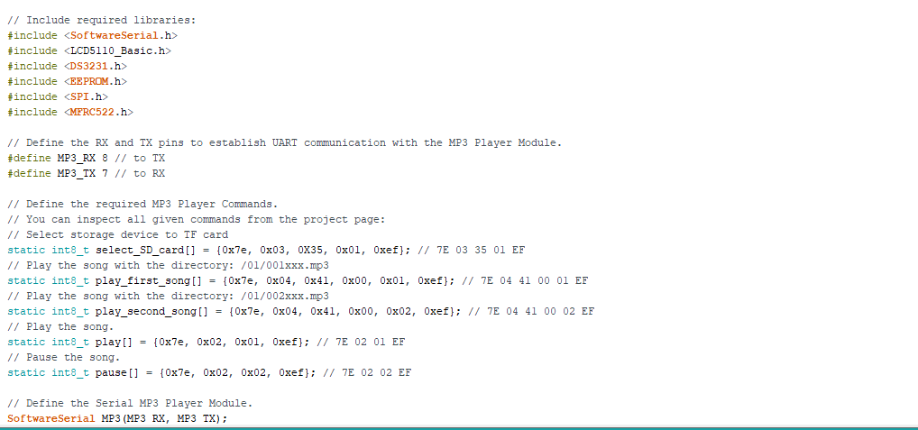
- Include required libraries after downloading.
- Define the RX and TX pins to establish UART communication with the MP3 Player Module.
- Define the required MP3 Player Commands:
- 7E 03 35 01 EF (Select storage device to TF card)
- 7E 04 41 00 01 EF (Play the song with the directory: /01/001xxx.mp3)
- 7E 04 41 00 02 EF (Play the song with the directory: /01/002xxx.mp3)
- 7E 02 01 EF (Play or Continue)
- 7E 02 02 EF (Pause)
- Define the Serial MP3 Player Module by using the SofwareSerial library.
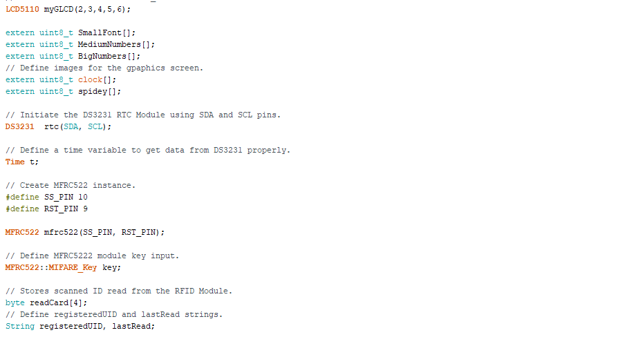
- Define the Nokia screen pins.
- Get the monochrome images for the graphics screen (clock and spidey).
- Initiate the DS3231 RTC Module using SDA and SCL pins.
- Define a time variable to get data from DS3231 properly.
- Create MFRC522 instance.
- Define MFRC522 module key input.
- Define the readCard byte which stores the UID scanned by the MFRC522 RFID Module.
- Define registeredUID and lastRead strings.
- Define the control button pin numbers.
- Define the interface menu commands (booleans).
- Initiate the Serial MP3 Player Module.
- Select the SD card as storage by sending the required command with the send_command_to_MP3_player function.
- Start the rtc object.
- Start the MFRC522 Hardware using SPI protocol.
- Initialize MFRC522 Hardware.
- Initiate the Nokia screen.
- In the read_control_buttons function, read the control buttons (Left, OK, Right, Exit).
- In the select_menu_commands function:
- Increase or decrease the option number using Right and Left buttons.
- Depending on the selected option number, change boolean status.
- In the home_screen function, print the interface (menu).
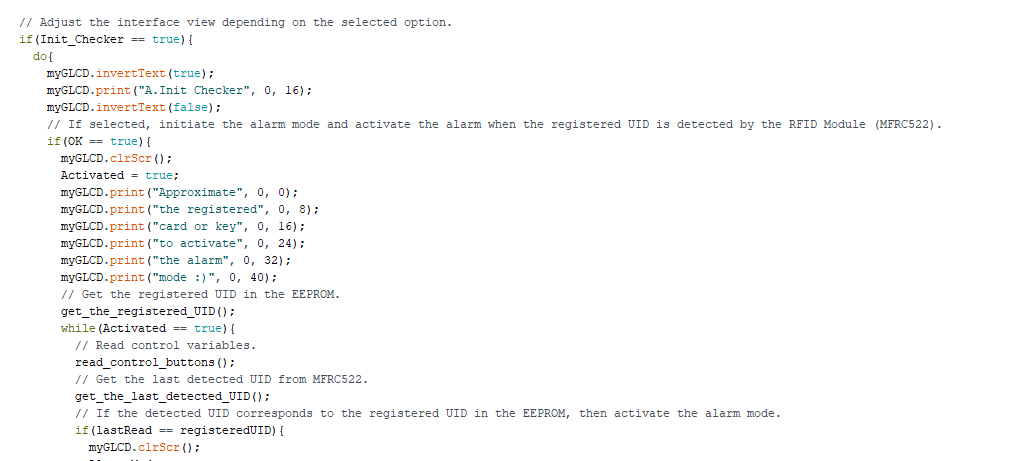
- Adjust the interface view depending on the selected option.
- If Init_Checker is selected:
- Initiate the alarm mode and activate the timer when the registered UID is detected by the RFID Module (MFRC522).
- In the get_the_registered_UID function, get the registered UID in the EEPROM and arrange it for comparing.
- In the get_the_last_detected_UID function, get the last UID detected when an RFID card or tag is read by the MFRC522 RFID module and arrange it for comparing.
- If the detected UID corresponds to the registered UID in the EEPROM, then activate the alarm mode.
- Draw the alarm mode icon (clock).
- Get the date and time information from the DS3231 RTC Module.
- If the timer (RTC Module) hits the given reading time, then start the MP3 Player (the second song).
- Draw the notification icon - I used a Spider-Man icon because the MP3 Player plays his cartoon's sountrack :)
- Play or pause selected songs for fun while the device is in the alarm mode :)
- Blank the lastRead string after false readings.
- If Set_Checker is selected:
- Set the reading time by using Left (-) and Right (+) buttons to get notified when the timer (RTC) hits the given time (such as 18 : 37).
- If Clock is selected:
- Monitor date, time, and temperature on the Nokia 5110 screen.
- In the get_time_rtc function, get the current hour and minute from the DS3231 RTC module - t.hour; t.min; - and set them manually by uncommenting the highlighted lines.
- If New_Card is selected:
- Scan a new RFID card or tag and save the new UID to the EEPROM as the registered UID to be used to activate the alarm mode.
- In the register_new_card function, detect the new card UID and save the new UID in the readCard byte to write it to the EEPROM.
- Return the success message ("Registered Successfully!").
Connections (PCB)
Connect the modules and Arduino Nano to the headers on the PCB (RFID Reading Time Checker) as follows.
A1 -> Arduino Nano v3
J1 -> Serial MP3 Player by OPEN-SMART
J2 -> MFRC522 RFID Module
J3 -> DS3231 RTC Module
J4 -> Nokia 5110 Screen
Integrated Components on the PCB (after PCBA):
R1, R2, R3, R4 -> 220-ohm resistors (buttons)
R5, R6, R7, R8, R9 -> 1K resistors (Nokia 5110 Screen)
K1, K2, K3, K4 -> Control Buttons
J5 -> Power Jack


Arduino Pin Connections Embedded on the PCB:
// Connections
// Arduino Nano v3:           //                                Serial MP3 Player Module (OPEN-SMART)
// D8 --------------------------- TX
// D7 --------------------------- RX
//                                Nokia 5110 Screen
// D2 --------------------------- SCK (Clk)
// D3 --------------------------- MOSI (Din) // D4 --------------------------- DC // D5 --------------------------- RST
// D6 --------------------------- CS (CE)
//                                DS3231
// SDA(or A4) ------------------- SDA  // SCL(or A5) ------------------- SCL
//                                MFRC522
// D9  -------------------------- RST
// D10 -------------------------- SDA
// D11 -------------------------- MOSI
// D12 -------------------------- MISO
// D13 -------------------------- SCK
//                                LEFT_BUTTON
// A0 --------------------------- S
//                                OK_BUTTON
// A1 --------------------------- S
//                                RIGHT_BUTTON
// A2 --------------------------- S
//                                EXIT_BUTTON
// A3 --------------------------- S
Demonstration and Conclusion
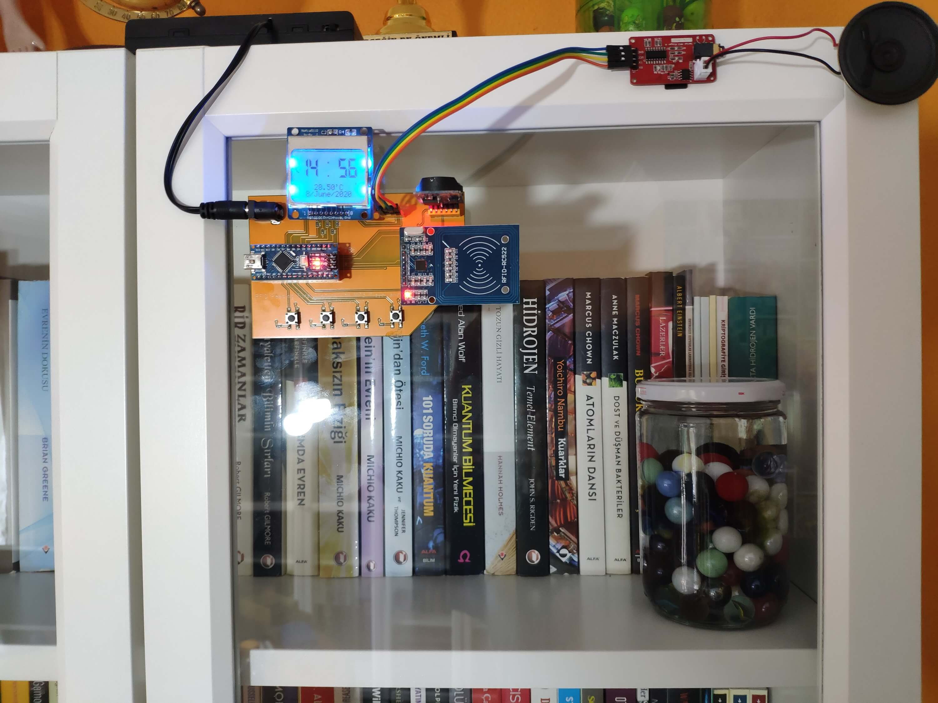
After completing the device, I fastened it to my bookcase by using a hot glue gun to activate the alarm mode with my RFID tag quickly when I get a book from my bookcase :)
