Click here to go directly to Digitspace's product page.
Constructing the camera
At first, putting together all the hardware components to construct the camera may seem intimidating to do, but from my experience, it is actually quite straight forward and can be done without any major difficulties. However, my number one tip is to make sure that the various components are put in the right place as some parts may visually appear the same but are slightly different in size or shape, like some of the acrylic parts and the screws. As a result, I recommend organising all the smaller components in groups first before starting as loosing parts can be a big issue for you as well.
Secondly, one of the small issues which I faced when building the camera was in regards to the wiring of the servo controlling the horizontal movement as you may need to force the connecting cable through small gaps to make everything work well. Nevertheless, it should not be a problem that will damage the cable or cause any open circuit, but I would advice you to try and use minimal force only when constructing any aspect of this product.
Lastly, make sure everything is tightened well at the end as that will ensure that the operation of the camera is smooth and works with no problems when put to the test. Refer to the video below on how to construct the camera from start to end (you can pause or slow it down to follow along at certain parts):
When mounting the plastic studs connecting the acrylic base piece to the Micro:bit expansion board, you may want to use a bit of force but make sure that it is positioned in the right direction first before pushing. Furthermore, be careful when positioning the camera in place as you would want it to be straightened out but without any damage to the antenna or the ribbon cable in the process.
Wiring the camera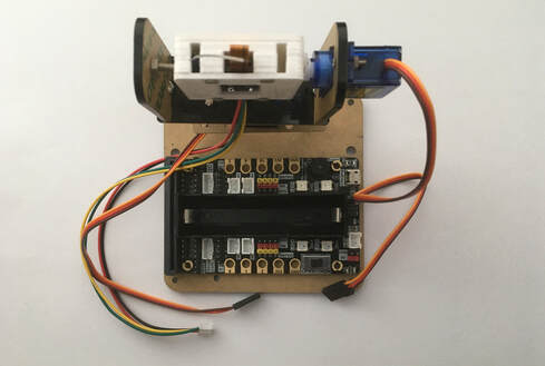 1. After the construction of the camera, we will need to connect a few wires from the camera and the two servo motors to the Microbit expansion board. First of all, make sure no power is connected to the Microbit, its expansion board or the camera itself.
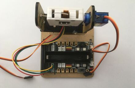
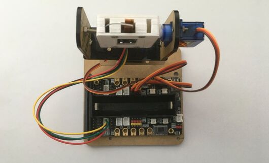
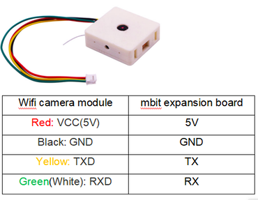 2. To start with, connect the camera's cable, the one with a male 4-pin JST connector on its end, to the female 4-pin JST connector located on the Microbit expansion board marked 'Serial Port'. There is only one direction which the JST cable can fit into the connector, so you don't need to worry about the polarity or the cable being placed in the wrong way. An image of the camera pinout is above for further reference.
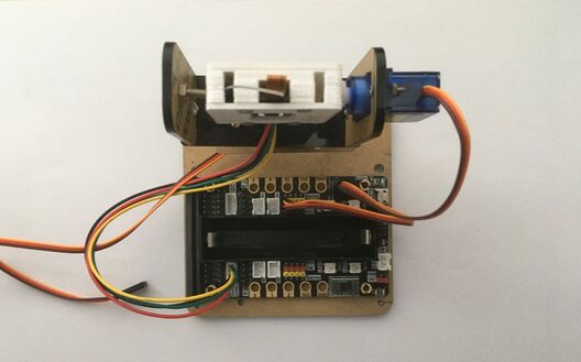 3. Next, for the servo motor controlling the vertical movement of the camera (up/down), connect its 3-pin wire to the row of male pins on the Microbit expansion board marked 'S1'. The three colours of the wire will match up to the three colours on the pins on the expansion board with the brown wire closest to the 18650 battery, so make sure that it is connected in the right way before powering anything up at the end.
 4. For the last wire, it connects from the servo motor controlling the horizontal movement of the camera (left/right) to the Microbit expansion board so connect its 3-pin wire to the row of male pins marked 'S2'. Once again, the three colours of the wire will match up to the three colours on the pins on the expansion board with the brown wire closest to the 18650 battery, so make sure that it is connected in the right way before powering anything up at the end.
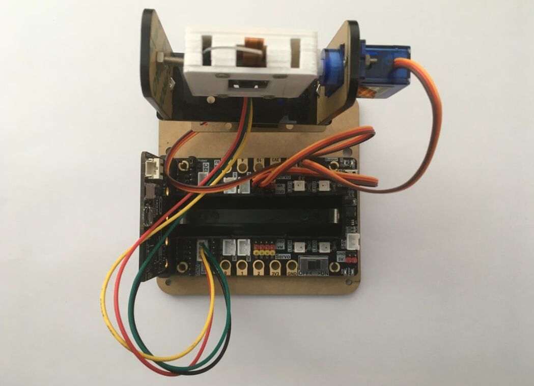
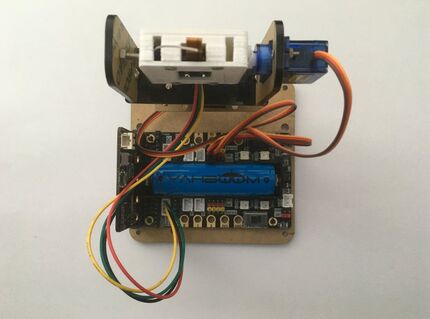 5. Now, to complete setting up the hardware part of the camera, you can insert the 18650 battery into the battery holder and the Microbit into the expansion board's port as seen with the final pictures above. Make sure that the polarity of the battery is correct as shown by the markings in the picture before turning on the power switch as well as the direction of the Microbit board in the port as shown above also.
Programming the camera
In regards to the coding aspect of the camera, we will be using the Microsoft MakeCode Blocks/JavaScript Code Editor which you can...
Read more »
 Gradivis
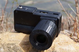
 Jacob David C Cunningham
 Human Controller
 Martin Fasani