DANTRACX
INVERTER MODULE OVERVIEW
All technical details and device specifications can be viewed from the github repository
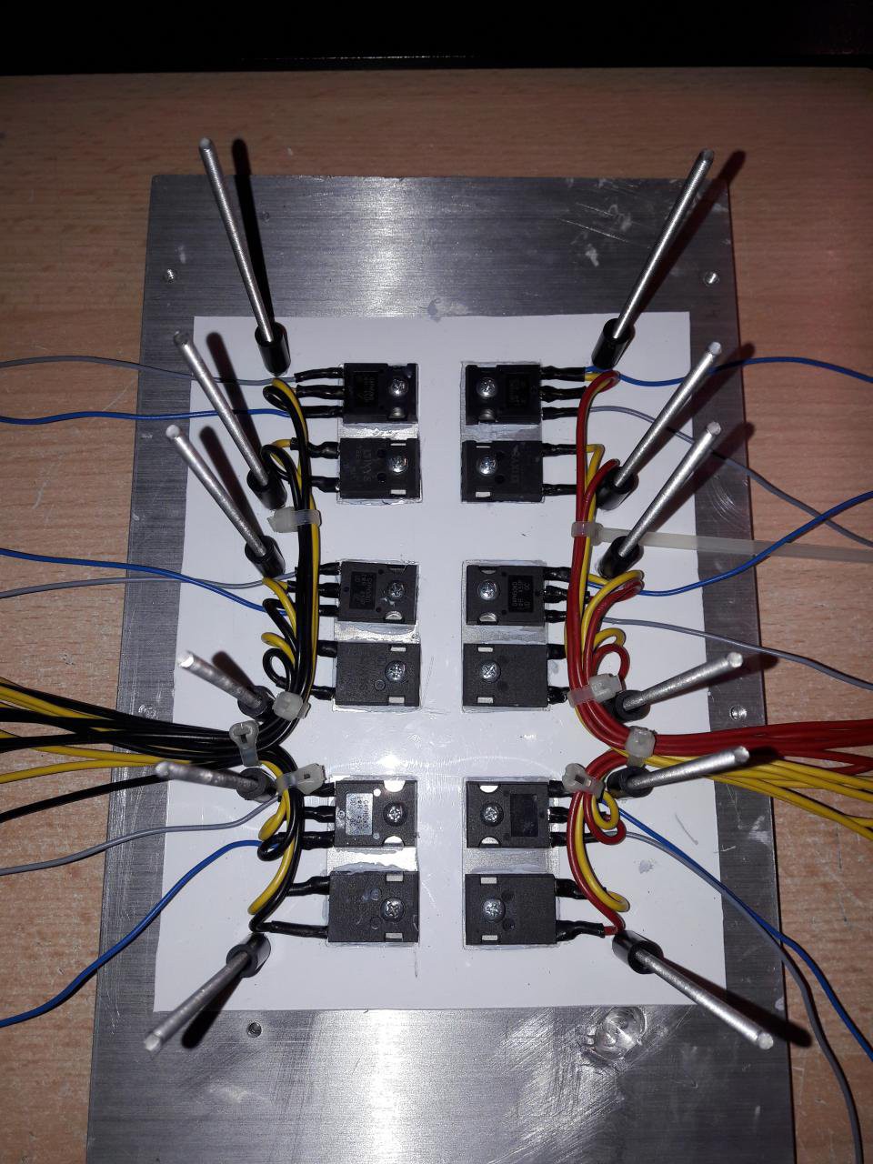
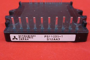
POWER MODULE
The power module consists of an aluminium base plate where 6 igbts and 6 diodes are mounted directly to the surface with a glimmer plate in between for adequate heat transfer and isolation. An additional isolation layer made from 5mm thick polypropylene is used to guarantee no harm due to isolation damage from any loose wires or connections. For this prototype, the target motor is a 2.2kW 380V three-phase induction maschine, so 1200V igbts with an Imax of 60A have been choosen to leave some margins for current and voltatage spikes.
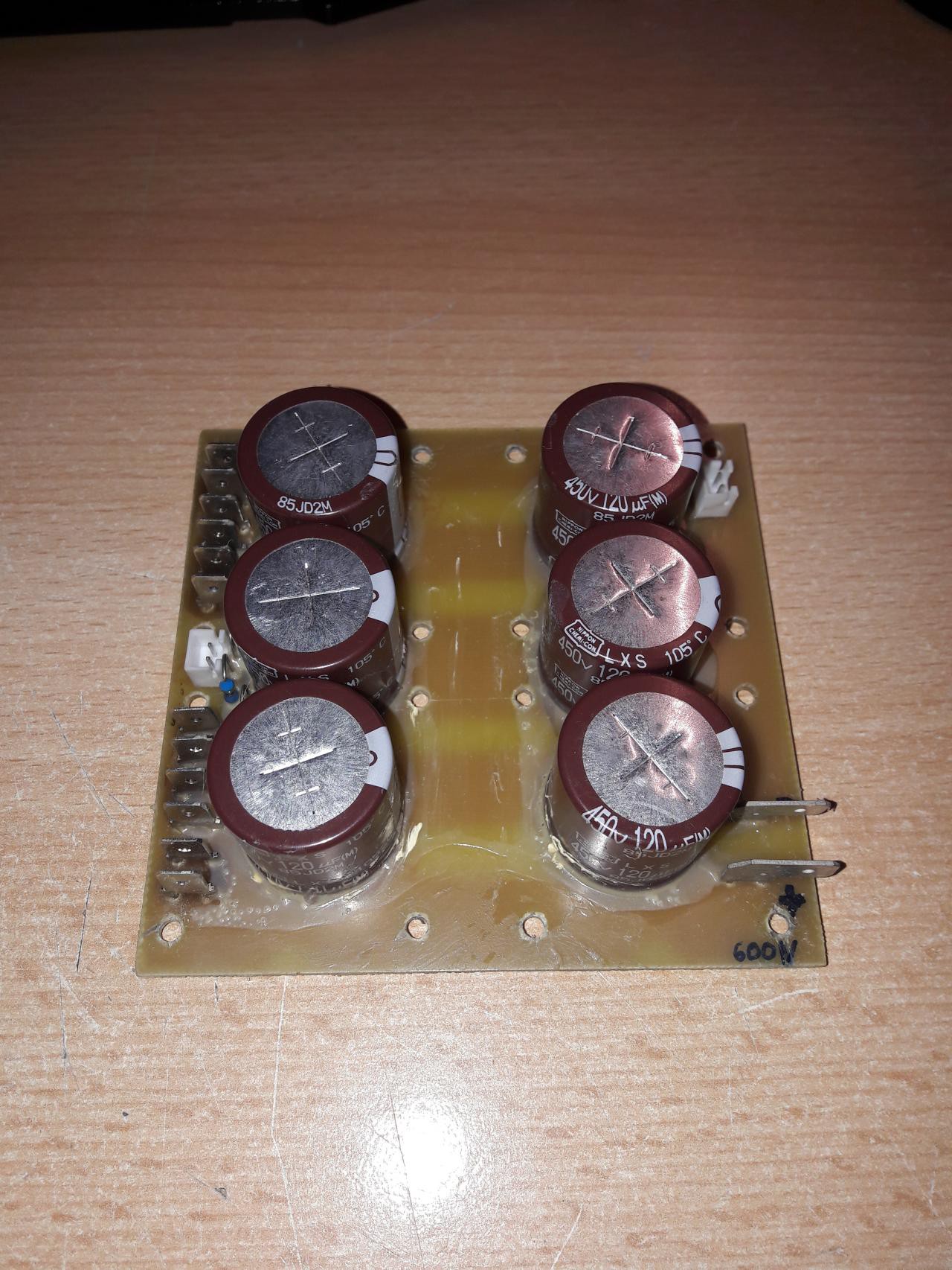
DCBUS
The DCBUS acts as a distribution layer for the wiring and holds the dcbus capacitors which are rated for 450V each, summing up to 900V. To increase the resistance against mechanical stress, the capacitors were glued to the PCB surface. Additionally a current shut for the dcbus current and a voltage divider for dbus voltage measurement were added. The target voltage for the dcbus is set to 600VDC which was chosen to match the target motor.
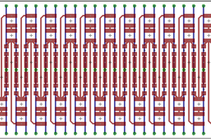
PHASE DISTRIBUTION
(work in progress)
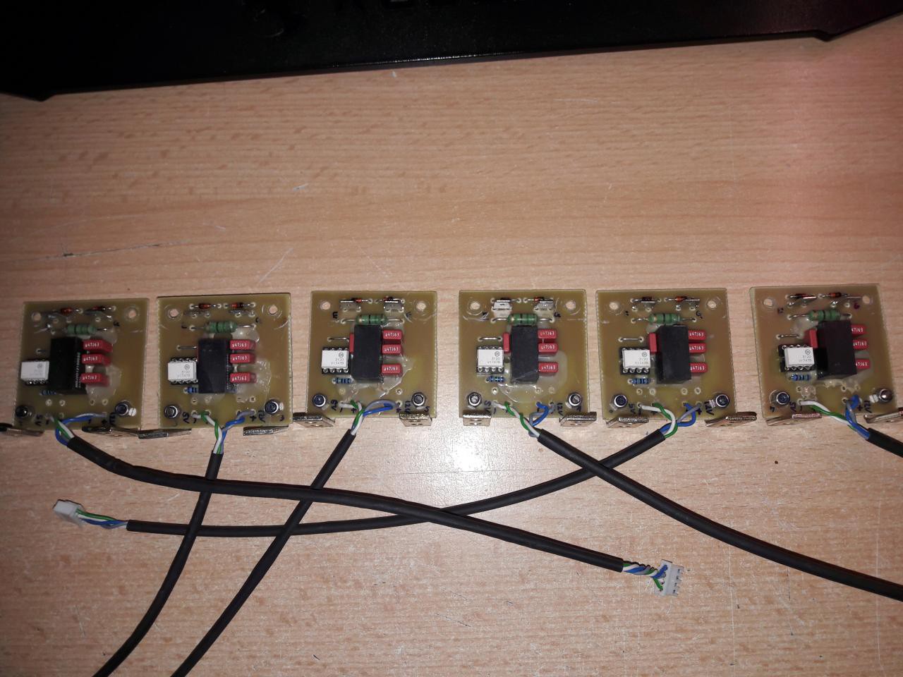
IGBT DRIVER
These are fully-isolated IGBT drivers with integrated gate resistor. The power signal as well as the logic signal are isolated for both low- and high-side. The DC/DC converters were chosen with enough spare power to drive even multiple igbts in parallel - if (for some reason) needed.
CONTROLLER
(text work in progress)
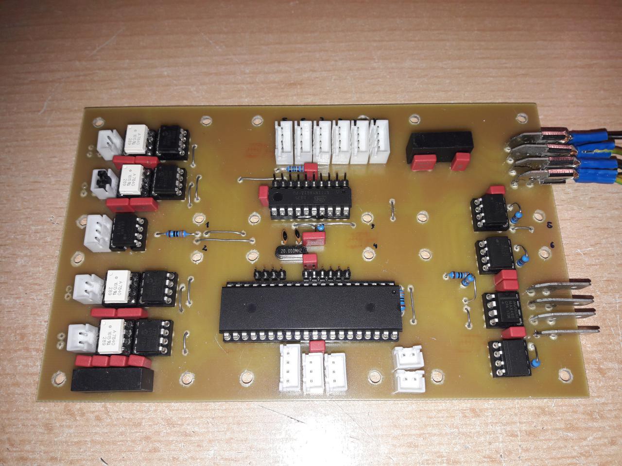
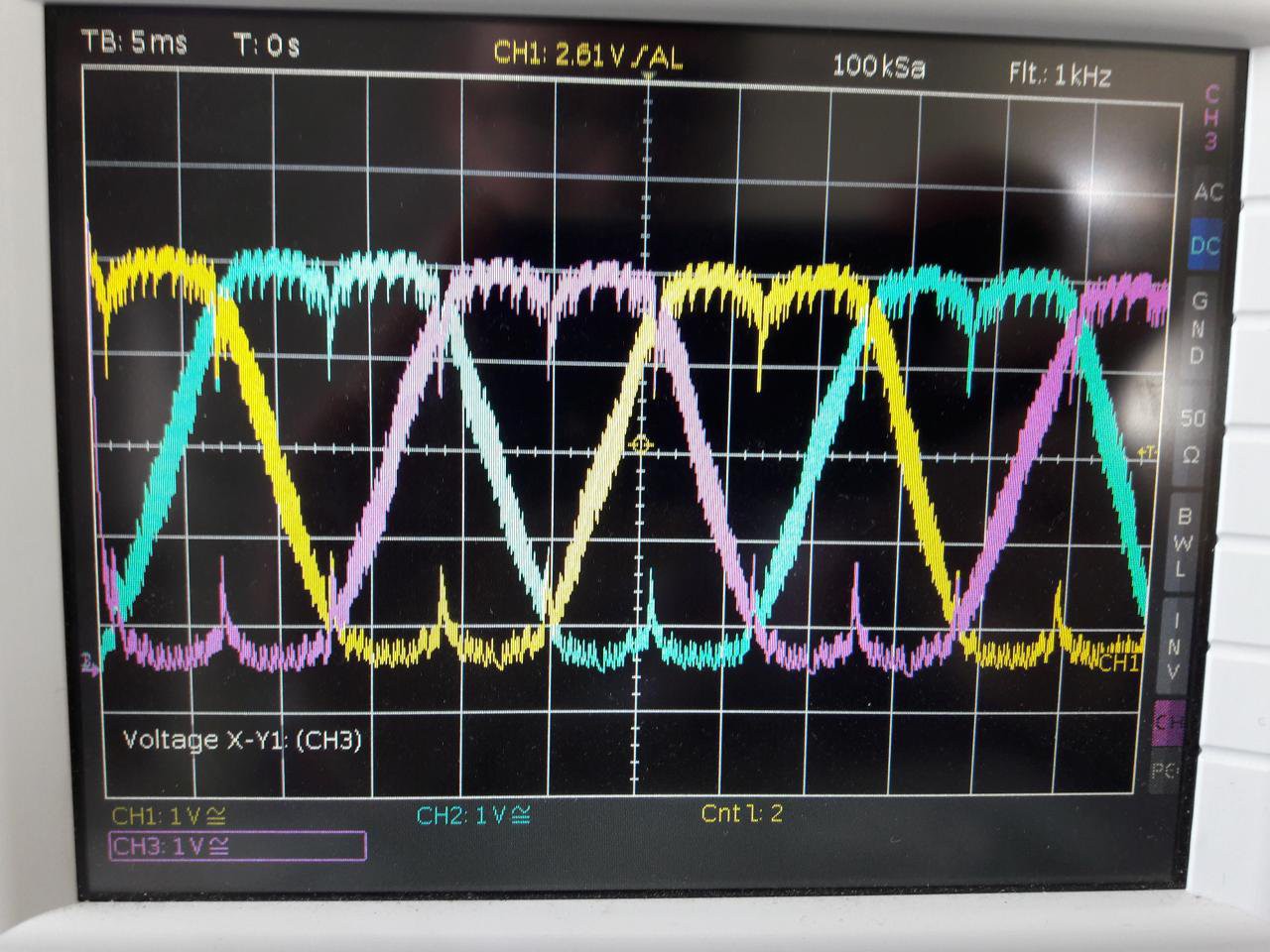
SVPWM-IC
The SVPWM-IC uses an Attiny861A which is generating a three-phase svpwm output with third-harmonic injection. It is entirely programmed in assembler in order to reduce interrupt overhead and speed up calculations. The main logic can send a control frame via the SPI interface which includes information about the amplitude (0-255), the freuquency(0-65535), the pwm frequency (1, 2, 4, 8, 16 kHz), the phase offset and the deadtime settings to eliminate simultanous on-switching.
LOGIC CONTROLLER
PARTIAL PFC
(text work in progress)
 Electroniclovers123