 Noeël Moeskops
This is the entry video for the Hackaday Prize 2020. It briefly shows the history of the project, the current state and the concept behind it. I hope you enjoy!
Challenge
Monitoring and observing life is an important aspect of getting an insight on the current state of animal life and if they are in danger of extinction. This can however be a difficult process to do if the life you are trying to monitor is in difficult to reach places, or even hazarded environments to humans like deep water bodies. The ocean is a very fast place with many species that may suffer the hardest from climate change. Therefore, it is important to monitor, inspect and preserve them as much as possible. From the tiniest sea creatures living on the bottom of the ocean to the school of flying fish. Currently, doing so is an expensive operation and require a lot of human labour and expensive equipment like ROVs (remove operate vehicle). A marine expert has to be present to analyse the data and draw conclusions. To do this in a continues matter would be a very cumbersome and expensive task. As new equipment for monitoring is being developed it may be difficult to adapt the already existing hardware to these new equipment.
Solution
I propose a low cost, highly modular ROV: Aruna, with specialized equipment that can be used for underwater monitoring and marine research. The ROV can have a wide range of sensor and equipment such as:
- Camera: This is not just useful for taking pictures and as a visual guide for controlling the ROV, but it can also be used in conjunction with an artificial network to automaticly detect fishes and counts them without user interference.
- Soil sampler: To inspect life at the sea floor a sample of the soil can be taken with the ROV. For later (or on-board) analysis.
- Water sample: To monitor the microscopic particles in the water like plankton or micro plastic particles. Samples can be taken from varying depths for further analyses.
- Tag system: tagging an animal to monitor its behaviour or dropping a node on an interesting side for continues analysis to be later retrieved.
- Microphone: for monitoring whale activity.
Any other equipment can be easily introduced later because of the modular nature of the ROV. The ROV was designed with modularity in mind, so it can be easily adjusted to the desired situation. The current design has 5DOF (degrees of freedom) using 6 propellers. Adding two extra propellers can be used to get full 6DOF. The model can also be substantially changed by converting it to a glider model, so it can be more effective on longer missions with greater distances where high mobility is not required. The high modular design of the ROV allows for all these adjustments and is at the heart of the implementation of the device.
Aside from the monitoring sensors described above a number of other sensors are to be used for navigation like gyroscope, pressure sensor, accelerometer, GNSS, compass and sonar. The goal is to allow the ROV to complete a mission with as little human interference as possible. Thus, the user can choice to deploy multiple ROVs at a site which all perform a set mission and communicate their findings back to the user. This could also happen periodicity so that a continuously monitoring function can be achieved. The user may also choice to manually control the ROV for precise missions, this is the current focus of the project.
Technique
Software
At the base of the project lies the Aruna C++ library. This library is build of multiple modules. The goal of these modules is to be written portable so that they may run on any platform. Beneath the modules are drivers-interfaces. These are abstract classes that divine the behaviour of the platform specific drivers. These are platform specific and need to be rewritten for every platform. Aruna currently has full support for ESP32 (using ESP-IDF 3.2.2), there is partially support for Linux. And lastly, planned support for the STM32 family.

Module |
Platform |
||
|
|
ESP32 |
Unix* |
STM32 |
Logging (log) |
v |
v |
v*** |
Communication (comm) |
v |
v |
x |
Safety instrumented system (SIS) |
v |
v** |
x |
Control |
v |
x |
x |
Blinky |
v |
x |
x |
* Only tested on Linux x86
** Performer and Reporter untested
*** Untested
Current modules are:
- Comm: used for communication with the surface. This is a communication protocol inspired by IP/TCP but with as little overhead as possible (and way fewer layers). It enables fast and easy peer-to-peer communication. There are currently Link drivers for RS-485(ESP32), Serial for Unix and radio communication using VLF is planned. For more information see the docs
- Log: this module is quite simple. Enables logging of an Aruna module with visibility and verbosity control.
- SIS: monitors the status of the ROV and reports though a comm channel. On the ROV a SIS Performer is started that will perform a critical system check (like water level in hull). The status of the system in then given to the reporter that will relay the message to the Watcher on the other side of the comm channel.
- Control: used to move the ROV around. This module is especially flexible, as it allows any sort of actuator set-up. Any axis can be registered for the driver-interface: Actuator. By simply telling the desired axis the module will comply with the available resources that it has. Different actuators can be put in an ActuatorSet to allow for complex movement that require two different axes to work together. More information about the communication with this module
- Blinky: this module is just for testing. Blinks a LED on the device on command.
Mechanical
There are several CAD models developed for the ROV. All the components for the ROV life in (or on) an 80 mm PVC pipe. A certain set of design rules are applied to ensure that the hardware is as modular as the software. All the components must be able to “snap-on” the pipe, as to not require drilling, glueing or any other modification of the main PVC pipe. This ensures quick and easy swap out of new components and grantees hull integrity. All the components on the inside are held together by four M4 threads. All the components have their own bracket to hold them into place.

For components on the outside there
is a bracket with four M4 screw holes to hold the BLDC (brushless DC)
motor or any other accessories. For more CAD object see the repository

Electrical
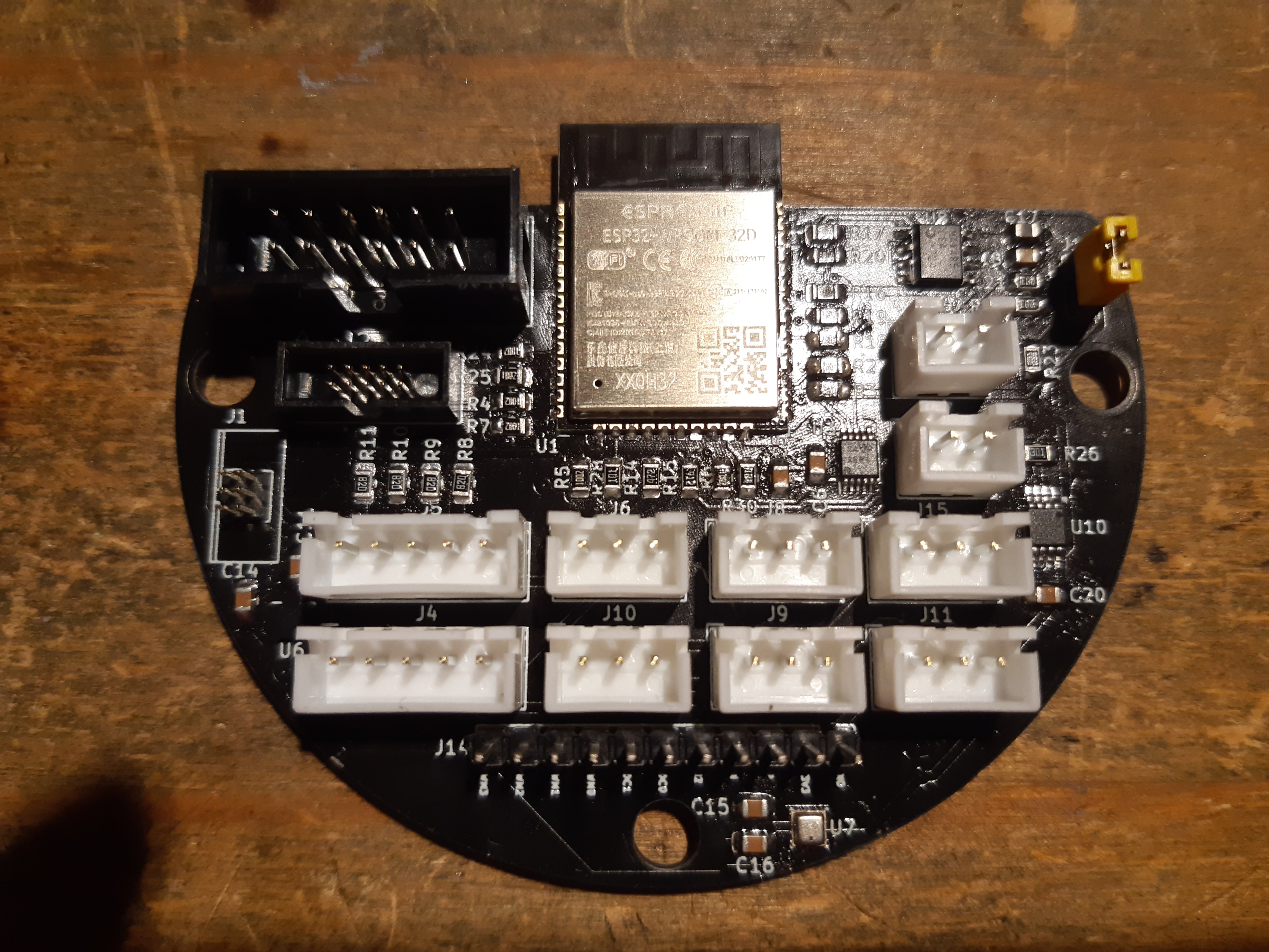
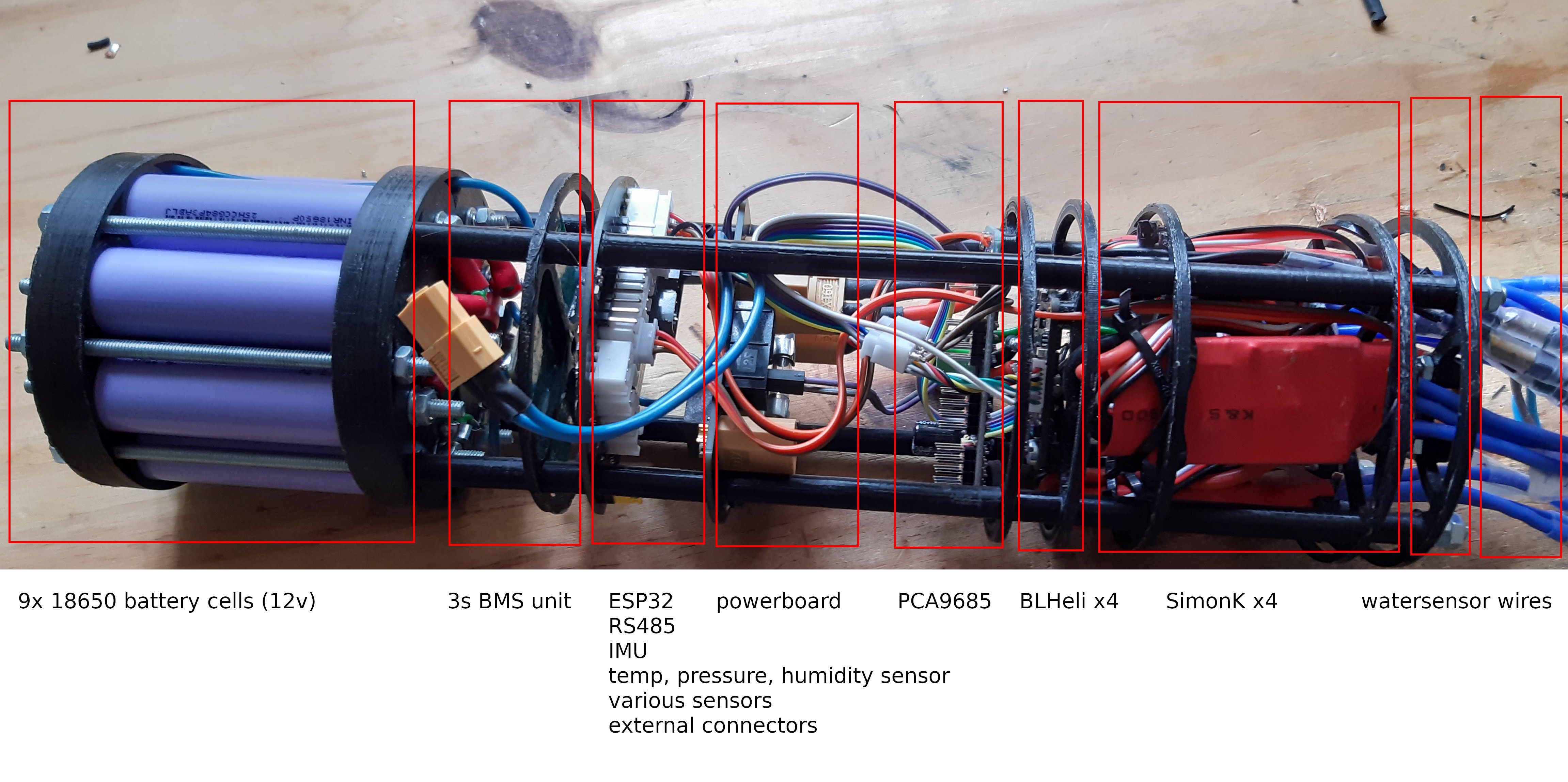
I have design several PCB's for Aruna that fit inside the 80 mm PVC pipe. The main board: Apsu is where the
all the control logic is situated and houses several connectors for external sensors like water temperature, water level and water pressure. But also a lot of sensors on the board itself like a IMU (Gyroscope, accelerometer and compass) and on-board pressure, humidity and temperature sensor. All the board have a 12 pin IDC connector with I²C, SPI, RS-485 and power so multiple boards can be daisy-chained together.
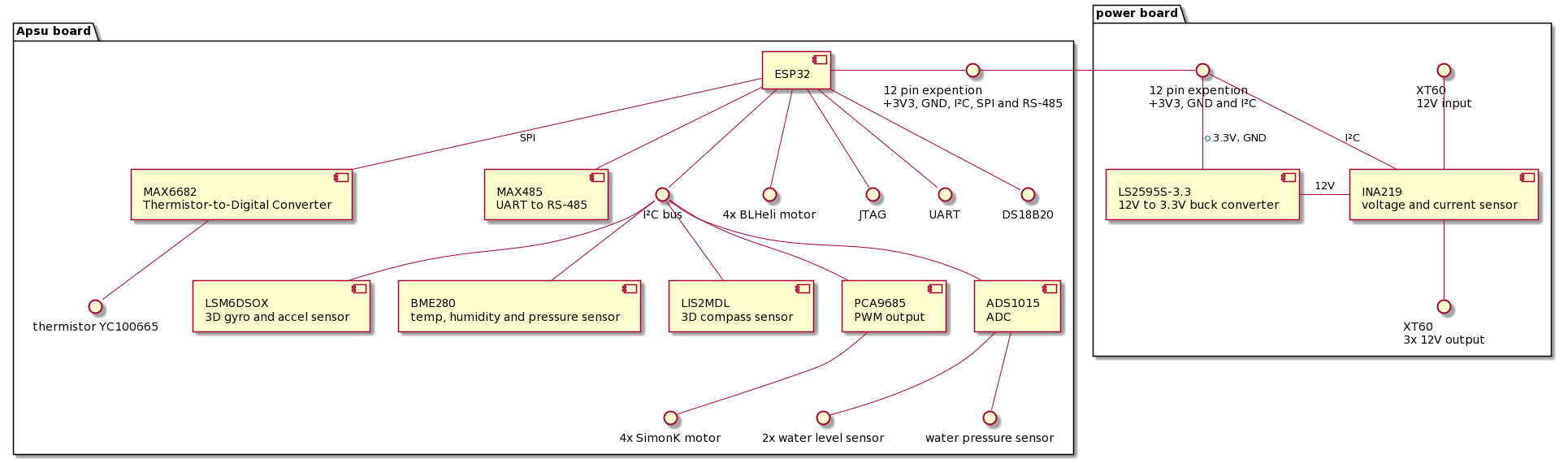
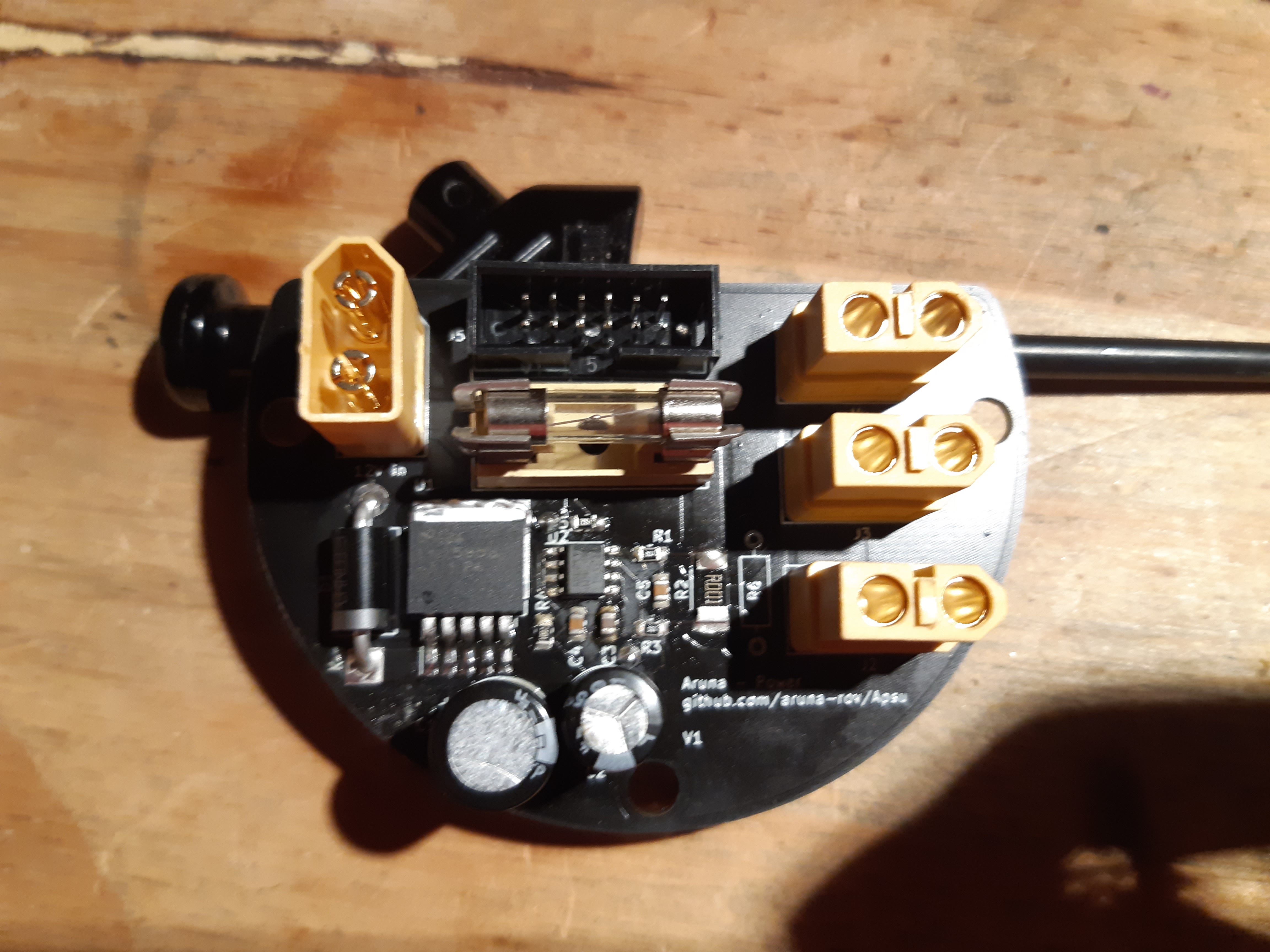
The second board is for power. This board converts the 12V of the battery to 3.3V for the internal logic and has several connections for the ESC motor controllers. It also measures the voltage and current.
See this log and future logs for more information.
Implementation
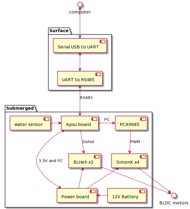
The current implementation of Aruna is quite bare. It consists of
a simple surface control software that allows for 4DOF movement by
keyboard input and monitors SIS reports. Attached to the computer
running the software is a serial to RS485 converter. The signal
travels back and forth to the ROV where the signal is feed into the
ESP32. The ESP32 controls the motors based on the command received
from the surface. Four SimonK drivers for forward, backward, sideways
and yaw. Two BLHeli controllers are used for upward and downward
movement. Water level is reported using a rain-meter. All written in C++ as described in the “software” section. The PCB design discussed in the "Electrical" features a lot of new features like an IMU, temperature, humidity, current, voltage sensors and connectors for more external sensors. These fancy features are however not yet implemented in software, but I'm working on that right now.
Four motors are attached to the outside of the PVC pipe in a diamond shape (see figure) to allow for 3DOF using just four motors that can only spin in one direction. The upward and downward motors are driven by BLHeli controllers and thus support clockwise and counter-clockwise rotation. See table for more information.
Axis |
Motor |
|||||
|
|
1 |
2 |
3 |
4 |
5 |
6 |
X+ |
N |
N |
Y |
Y |
N |
N |
X- |
Y |
Y |
N |
N |
N |
N |
Y+ |
N |
Y |
N |
Y |
N |
N |
Y- |
Y |
N |
Y |
N |
N |
N |
Z+ |
N |
N |
N |
N |
Y |
Y |
Z- |
N |
N |
N |
N |
Y (counter) |
Y (counter) |
Yaw+ |
N |
Y |
Y |
N |
N |
N |
Yaw- |
Y |
N |
N |
Y |
N |
N |
Pitch |
Not possible with current configuration. |
|||||
Roll+ |
N |
N |
N |
N |
Y |
Y (counter) |
Roll- |
N |
N |
N |
N |
Y (counter) |
Y |

Repositories
The Aruna project currently consist of five repositories.
- Aruna: this is the base of the project and consist of the C++ library with different logic modules and platform specific drivers.
- Apsu: is an ESP32 implementation of the Aruna library to be used as main ROV controller.
- Inar: desktop Posix (only tested on Linux x86) application for controlling an Aruna enabled ROV.
- Enki: effort to implement Aruna for an STM32 controller (still in development)
- ROV-CAD-objects: houses all the CAD object that are used.
- usb_to_rs485_over_rj45: schematic design for a USB to RS-485 converter. To enable easy communication with an Aruna ROV.