 Noeël Moeskops
ADS1015
The ADS1015 converts analogue to I²C signal (12 signed bit). This is necessary because there are no more pins left on the ESP32. The ADS1015, part of the ADS101x family supports four analogue inputs and have some nice comparator functions and an interrupt feature, so that there is no need to continuously read the analogue value of a pin but instead be warned when it reaches a certain (programmable) threshold. This does however require that the RDY/ALRT pin is connected to an input pin of the I²C master, unfortunately there are no i/o pins left, so I can't make use of this function.
Driver
The driver created for this IC is straightforward and currently only supports reading of a pin. Normally I create a driver for a specific module, like UART for `comm` or a stepper motor driver for the `control` module, but the ADS1015 can be used by multiple modules so the driver is situated in the `aruna::driver::ADS101x` namespace. In the future I want to refactor all drivers to here to make it consistent.
Files
- `./aruna/include/driver/ADS101x/ADS101x.h` defines the functions that a platform specific drivers should implement.
- `./aruna/include/driver/ADS101x/ADS101x_map.h` contains all the registers in class enums for easy driver writing without magic numbers.
- `./aruna/src/driver/ADS101x/ADS101x.cpp` implements an abstraction function `read(...)` that converts the value from the I²C bus to actual voltage and writes default values to the config register.
- `./aruna/src/driver/ADS101x/portable/ESP32/ADS101x_ESP32.cpp` is the only peace of the driver that is not cross-platform and only implements the physical I²C bus communication.
Adding support for new hardware is really easy, just create a `./aruna/src/driver/ADS101x/portable/xxx/ADS101x_xxx.cpp` file and implement `int16_t readConversion(uint16_t config, uint8_t address)` and all the middleware drivers like `ADS101xWaterSensor.cpp` that uses the ADS101x to read an analogue water level value will work flawlessly on new platforms. In the future I want to make a total abstraction for I²C, so you only need to implement `read()`, `write()` and `setup()` and can then freely use all the I²C drivers.
PCA9685
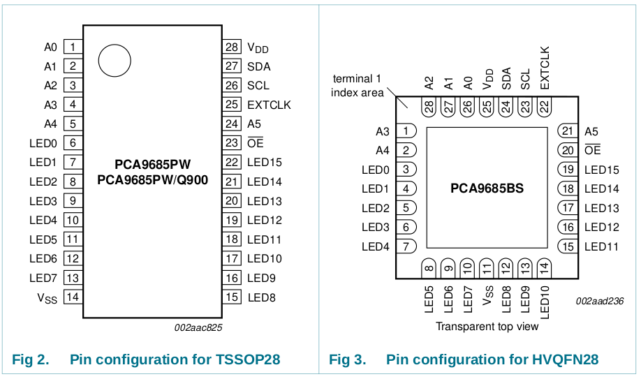
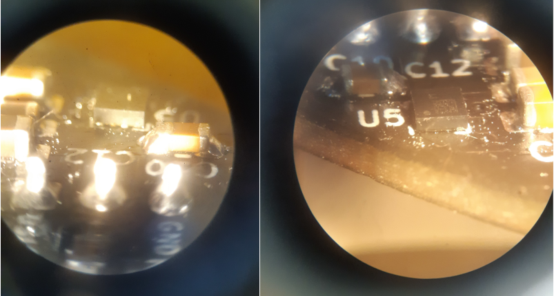
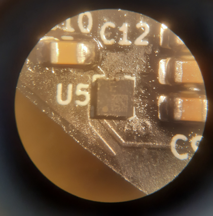
When testing the IC it turned out it didn't acknowledge I²C messages to its address (0b1000000 by default). After inspecting the IC with my microscope I saw that not all the connections were making solid contact. So I re-soldered the chip (two times in total) but still no dice. I then went thought the documentation and it turned out I used the wrong pinout of the PCA9685 in my design. In my initial design I used the PCA9686PW that comes in a TTSOP28 package, this was later switched to the HVQFN28 package because of space limitations. I however did not notice the pin difference between the two packages (see picture above, for example: A0=1 on PW while A0=27 on BS). So the pinout of the PCA9685 make no sense now on the PCB. I might be able to cut some traces and cross wire pins so that the chip can still be used.
LSM6DSOX
The LSM6DSOX is a 3D gyroscope and 3D accelerator sensor that using I²C (or SPI) to communicate the data. I want to use this to measure the speed of the ROV so that I can control the ROV by setting the speed and using control logic like PID to maintain a certain speed. The gyroscope comes in handy to stabilize the ROV and to know the orientation of the device.
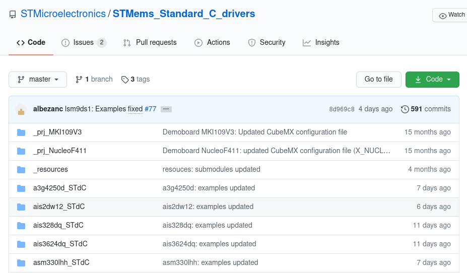
The LSM6DSOX has a lot of I²C registers so writing a driver from scratch just for testing is quite hard. Luckily it turns out that STM already created drivers for all their MEMS sensors, that need only an implementation of `read()` and `write()` for the platform specific I²C communication. Really some cool stuff. I implemented the platform specific function and ran the "self test" example. The test however, came back negative. It seems that communicating with the chip goes fine up to the point that you actually want to get any gyro or accelerator data of out it. It just returns gibberish. Debugging using a logic analyser shows a lot of I²C communication that all seems to be within the I²C spec. I then tried the Adafruit LSM6DS library for Arduino. This implementation fails to write to the I²C bus at the point of reading any measurement value. Or it gets a buffer overflow when reading data.
Edit: After sending ACK messages as described in IIS2MDC the chip passed the self-test successfully.
BME280
This bosh sensor measure the temperature, air-pressure and humidity. The air pressure and humidity are used to check for any leaks in the hull. By monitoring the humidity for any certain peaks and the pressure for drifting it can be concluded as a leakage. It is important to have multiple ways of checking if the system is in a safe state. If one system may fail then the leak can still be detected by another system.
This was the most expensive component on the board, so I was really hoping to have more luck with it then the last two IC's. Luckily the chip works immediately when using the Sparkfun BME280 library. The Temperature increased when I put my finger on the chip and humidity increased when breading on the chip. Very nice results, I guess you get what you pay for. Only the pressure reading where a bit off and need to be calibrated. But that was to be expected.
IIS2MDC
I originally picked the LIS2MDL, a 3D magneto sensor as a compass. But it was unavailable at Digikey. The IIS2MDC was however available and after reading both data sheets the only difference between the two chips I could find is that the LIS has one extra register for 3 wire SPI and a minor difference in maximum value.
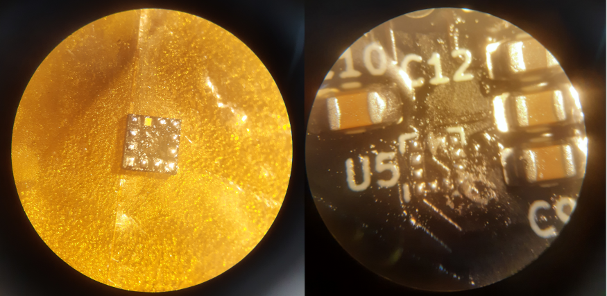
The IIS2MDC function is to get the heading (compass) of the ROV, and in doing so complete the IMU (Inertial Measurement Unit) sensor stack. The data is transmitted using I²C. This sensor is also made by STM and a driver is also available in their STMems git repo. I however have not yet come to the point of trying that driver because it is not sending acknowledgements when addressing the IC over I²C. And after some investigation it seems that there was a cold connection between the IC and the PCB.
I removed the IC and discovered that two pads had no solder on (I²C-SDA and one ground pin). After applying some more solder to the pins in question I re-soldered the chip and found that it finally replied to I²C messages :).
I could not find any readily IIS2MDC libraries for ESP32 or Arduino to test the functionality of the chip, so I tried an Arduino LIS2MDL library instead since the registers are almost identical. The ESP32 unfortunately called an `abort()` halfway through the test, I did not investigate further since the library compatibility was a long shot anyway. Instead, I tried the STMems C driver but was faced with the same issue as with the LSM6DSOX. Configuring the device went fine but actually doing a useful read of the magneto sensor resulted in failure. Since both sensors were failing in the same way gave me an indication that the chip and the PCB layout may not be faulty. It instead turned out that the I²C read messages were not being acknowledged by the master. I tried sending ACK's before but when I configured the driver that way the ESP would crash, so I left it disabled. Acknowledging all messages except for the last byte works though.

After setting the driver to `I2C_MASTER_LAST_NACK` I was finally greeted with "SELF TEST - PASSED". This also fixed the issue with the LSM6DSOX, two birds with one stone.
Only two ICs remain, the MAX6682 over SPI for thermistor reading and the INA219 for voltage and current sensing. But I'm afraid those will have to wait for the next log as this one is getting quite long and I'm tired of debugging all day.
Discussions
Become a Hackaday.io Member
Create an account to leave a comment. Already have an account? Log In.