 Noeël Moeskops
INA219
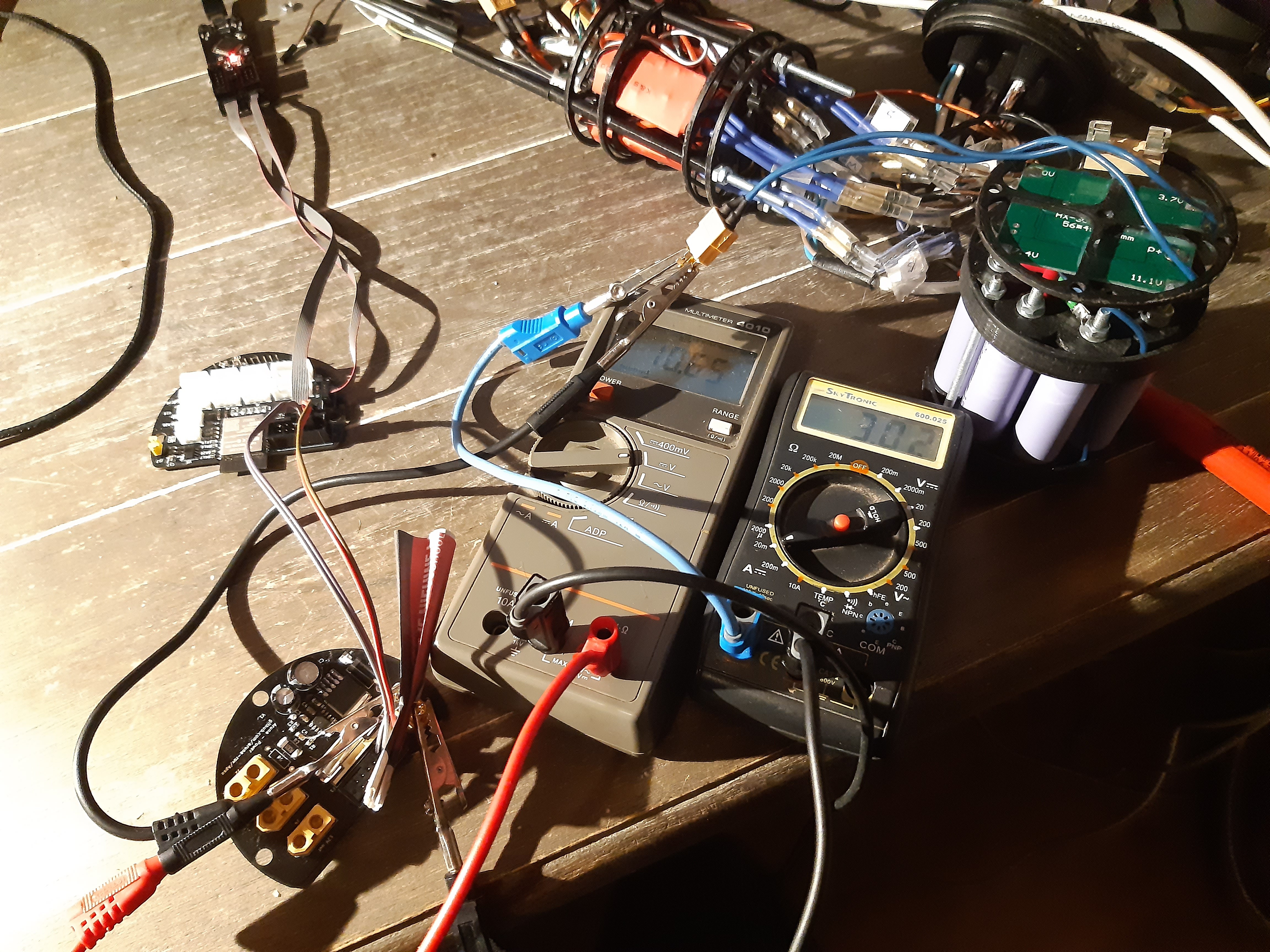
The INA219 is positioned on the power board to monitor the voltage and current of the 12V battery pack, communication goes over I²C. I used an Arduino sketch to test this sensor and it all worked the first try.
Bus Voltage:   10.62 V
Shunt Voltage: 0.54 mV
Load Voltage:  10.62 V
Current:       5.40 mA
Power:         59.00 mW
Serial output of the example code above.
MAX6682
The MAX chip converts thermistor temperature to digital data over SPI. This comes in handy for my external thermistor (YC100665). The chip takes care of self heating and power-supply noise and supplies a read-only 10bit SPI signal, very straight forward.
After reading the SPI documentation of the ESP-IDF it turned out that my assumption of "ESP-32 supports every hardware operation on every IO port" was incorrect. It turns out that there are two SPI IO sets for the ESP: HSPI and VSPI. HSPI is already in use by JTAG so only VSPI is left for mortals. Not using the VPSI pins is possible but at lower speeds and more delay. So not a total loss I though, until I found out that I was using an input only pin for the MOSI :( (also for one BLHeli Dshot output pin, but that was redundant anyway). I changed the MOSI pin to IO2, since that was the only pin left, so I could at least still test the chip.
The Slave Select pin of the MAX6682 is connected to an output of an MC74HC138A demultiplexer. This allows for up to eight devices on the SPI bus by using SS0-2 pins for chip selection. My luck turned here and I could successfully read the MAX6682 via SPI (no thermistor attached).
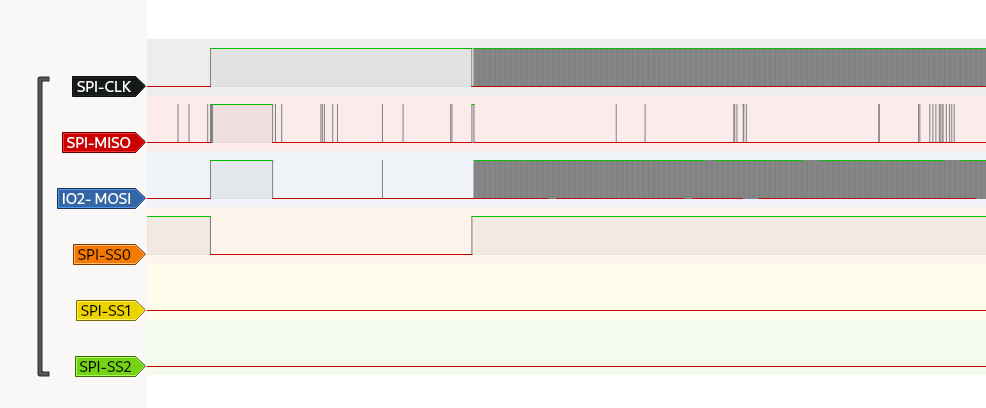
Looking at the logic analyser the data does not seem to make a lot of sense. At least the MAX6682 is outputting data on the MISO line. More testing with the sensor attached needs to be done. But I'll leave that for later since I want to focus on more essential things first.
Discussions
Become a Hackaday.io Member
Create an account to leave a comment. Already have an account? Log In.