 Noeël Moeskops
In the PCB tests log I talked about having the wrong layout for the PCA9685 IC (I used the TTSOP28 pinout with the HVQFN28 package). In order to solve this I considered four options:
- Cross wire and cutting traces to connect the correct pin.
- Buy external PCA chip
- Design breakdown board for the PCA.
- Designing Apsu PCB V2
I kinda wanted to have PWM control as fast a possible because its such a vital part of the ROV. So I opted for the first option of cross wiring the IC, because it could be done within one day (or, so I thought).
Of the total 28 pins of the PCA chip only 9 vital (+4 non vital) pins needed to be rerouted:
| pin nr. | PCA9685PW/TSSOP28 | PCA9685BS/HVQFN28 |
| 11 | led5 | VSS |
| 20 | led13 | ~OE |
| 21 | led14 | A5 |
| 22 | led15 | ext clock |
| 23 | ~OE | I²C SCL |
| 24 | A5 | I²C SDA |
| 25 | ext clock | VDD |
| 26 | I²C SCL | A0 |
| 27 | I²C SDA | A1 |
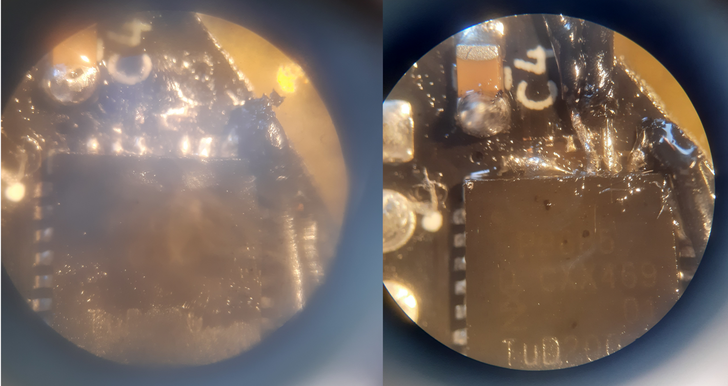
Soldering wires on the tiny connections was a frustrating task. The pad of pin 25 (middle pin in the left picture) was even broke due to extensive heat. And I also broke a solder tip (don't ask how). Luckily I managed to solder directly to the IC and connected pin 25, 26 and 27 to VCC. As can be seen on the right picture.
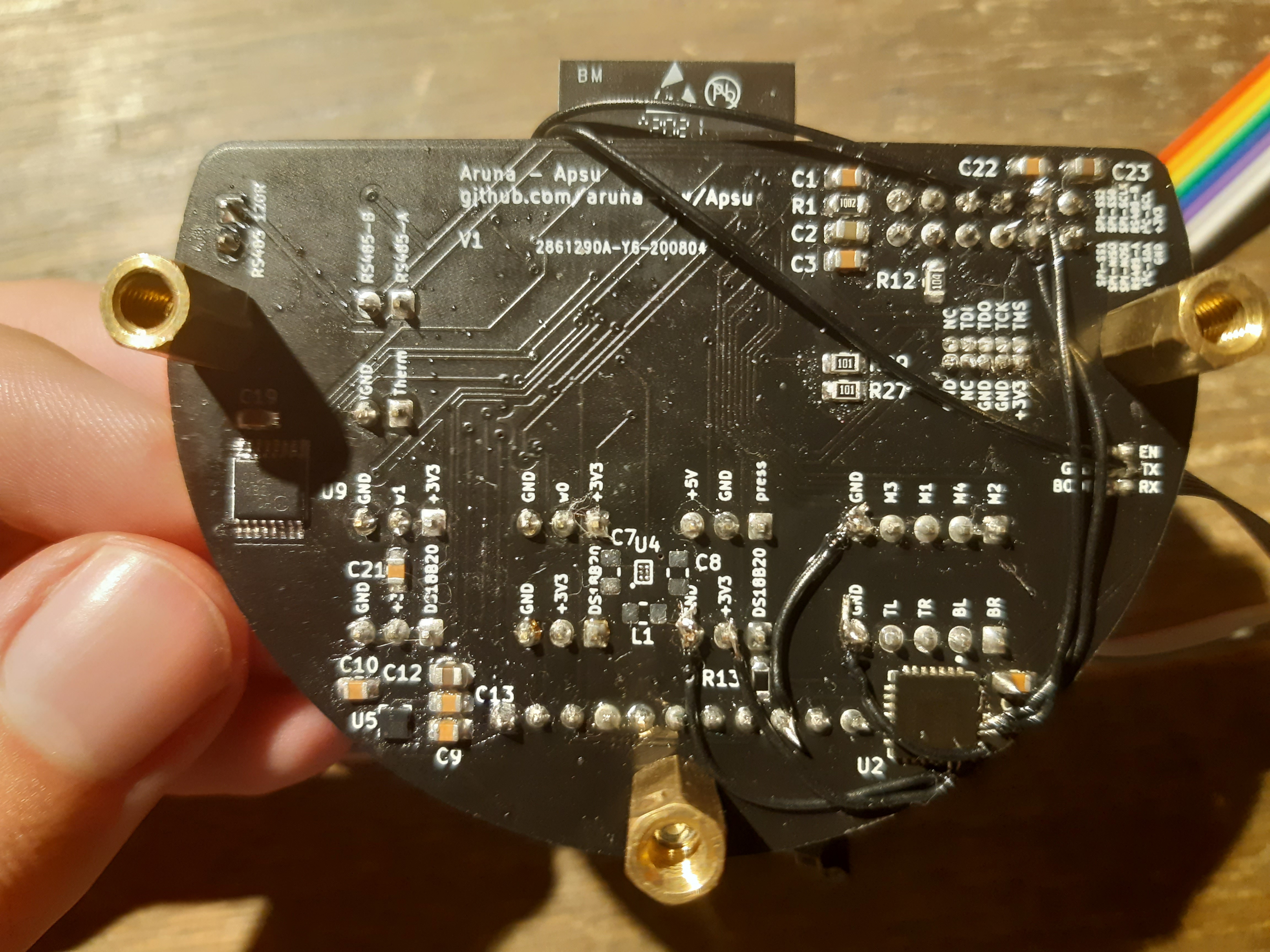
While cutting the traces I however, also cut the I²C-SCL trace. I didn't notice it at first and thought that I blew up the IO pin on my ESP somehow. So I needed an extra wire going from I²C-SCL directly to the ESP (top wire on the picture). After the complete rewiring the PCA now has the address `0b1100111`. And the Adafruit PWM library finally was working properly.
Discussions
Become a Hackaday.io Member
Create an account to leave a comment. Already have an account? Log In.