 Noeël Moeskops
After finishing writing the driver and confirming
that it was working with my logic analyser I connected my SimonK ESC. Unfortunately The ESC weren’t armed by the PCA PWM signal. I tried
changing the frequency of the PWM from 200Hz to 50Hz. But no dice,
after that my FT2232H JTAG debugger could no longer connect to my
ESP. It kept saying “could not halt device: not initialized” (or
something similar, I’m typing this from memory). It
turned out however that there was a short between
my ground and power (~20 Ohms). But I did not know
where. I first assumed it was the PCA9685 since it was directly
connected to an external chip and had experienced
mayor re-routing.
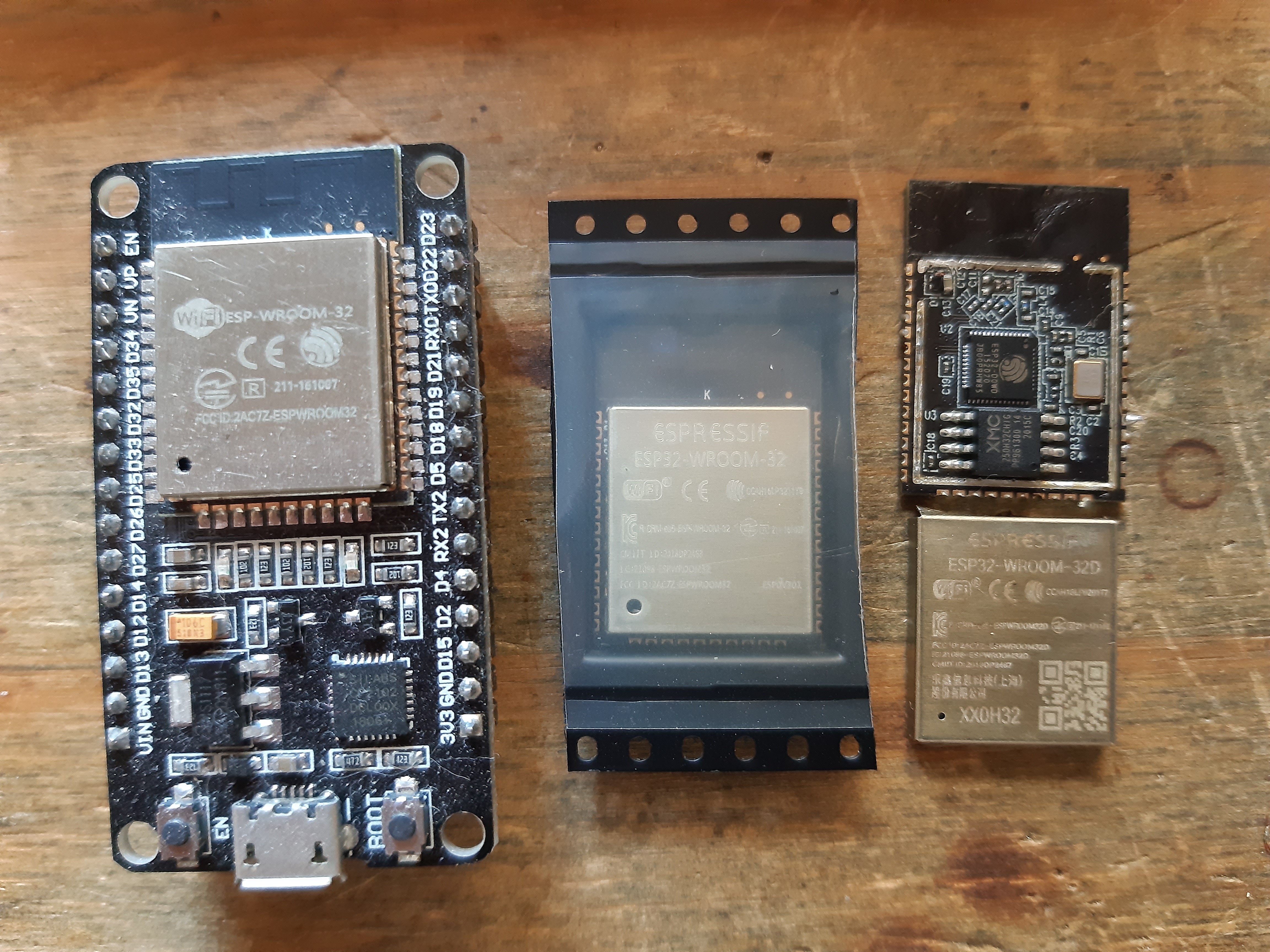
After desoldering the PCA9685 the short was still present. I removed the ESP and that mitigated the issue. Luckily I had a spare ESP-32 chip however, I messed up the SPI-SS0 pin. So SPI communication will be a little difficult. But that will be an issue for later.
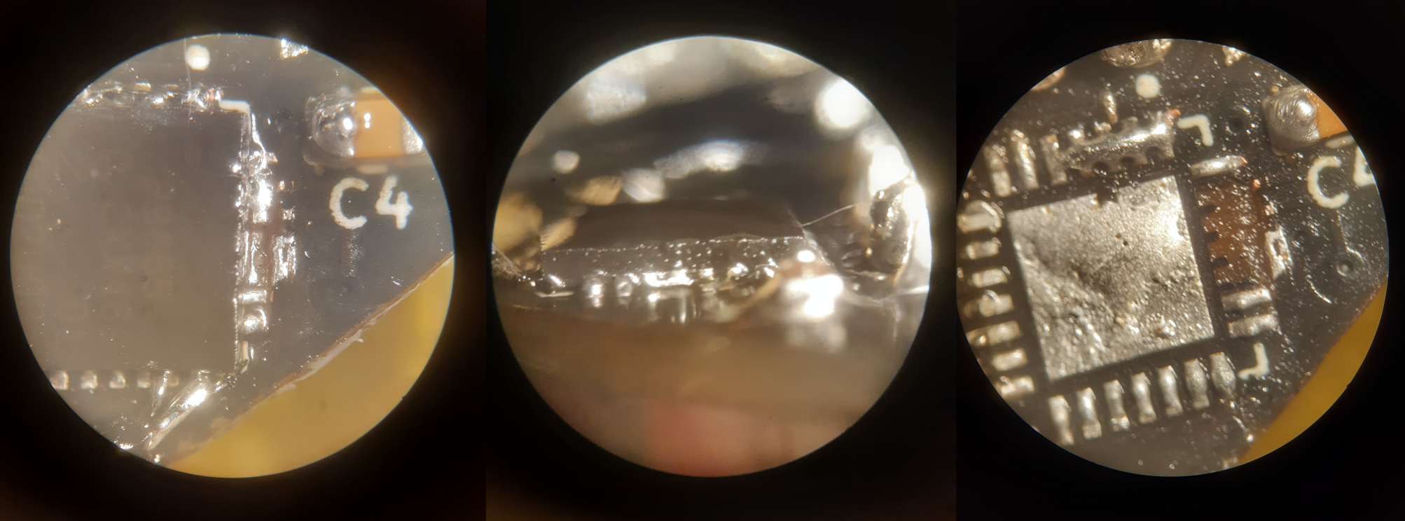
After measuring the PCA it turned out to be fine. So I tried to reinstall the PCA chip with all its tiny rerouting. This however did not succeed and I ended up destroying three more coper pads.
Since the PCA was beyond repair this time I opted for my second option discussed in previous log; to buy an PCA9685 breakout board. While connecting this to the Apsu board I was afraid that the shortage that happened earlier would strike again. I’m still uncertain why the ESP chip failed earlier. So I measured the PWM signals coming out of the SimonK ESC’s. And they all measured ~5V. This is possibly because they are pulled-up and should not pose a problem since the PCA9685 supports 5V logic levels (while it's still driven by 3.3V). After connecting everything together I was finally greeted with a spinning motor :).
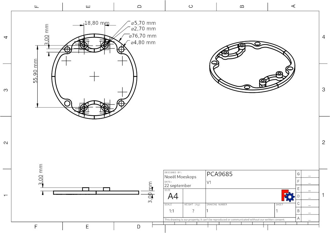
To enable the PCA9685 breakout board to fit into the tube of the ROV I created a holder for it. It looks very similar to the water holder breakout board I created earlier.
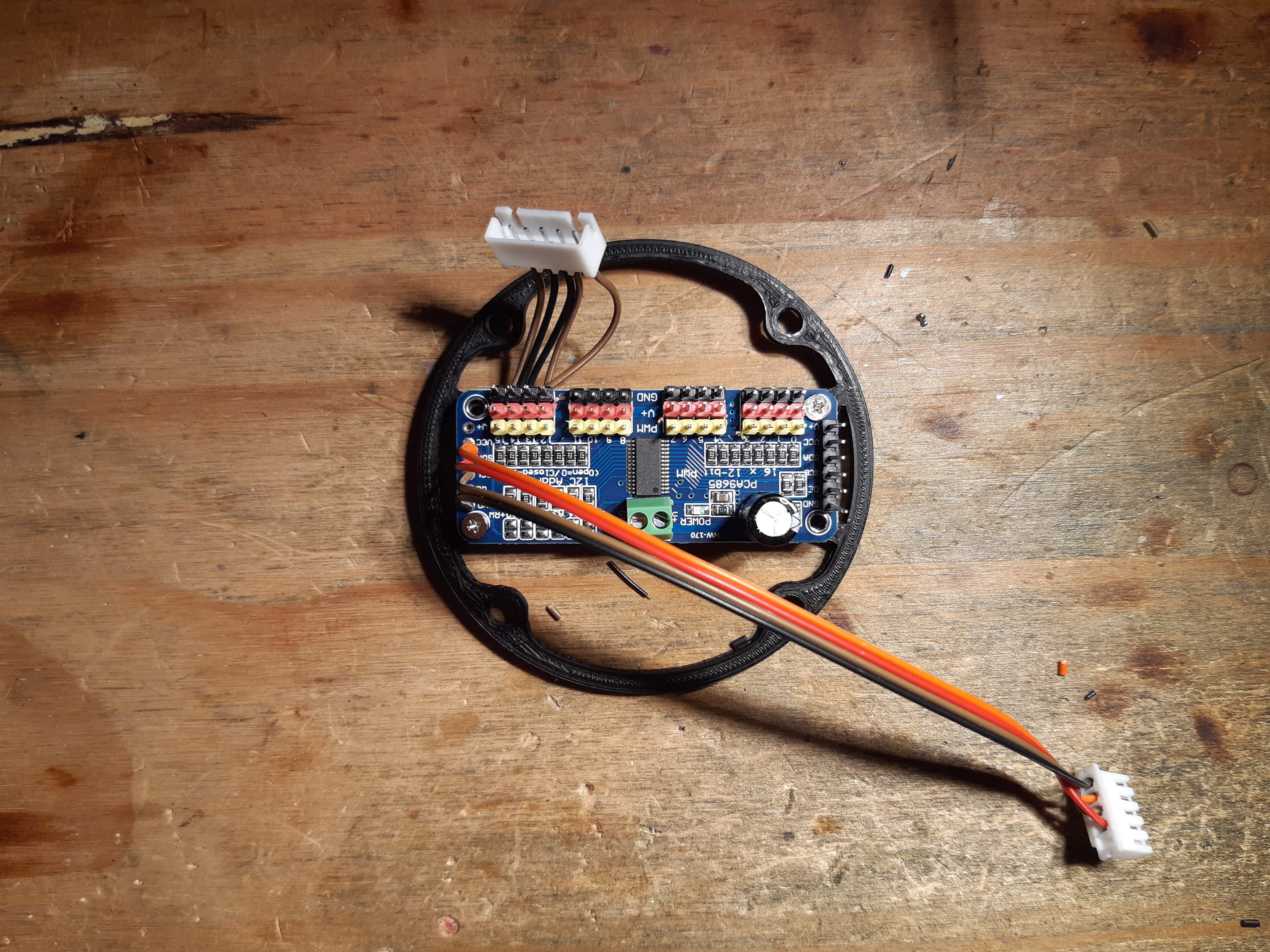
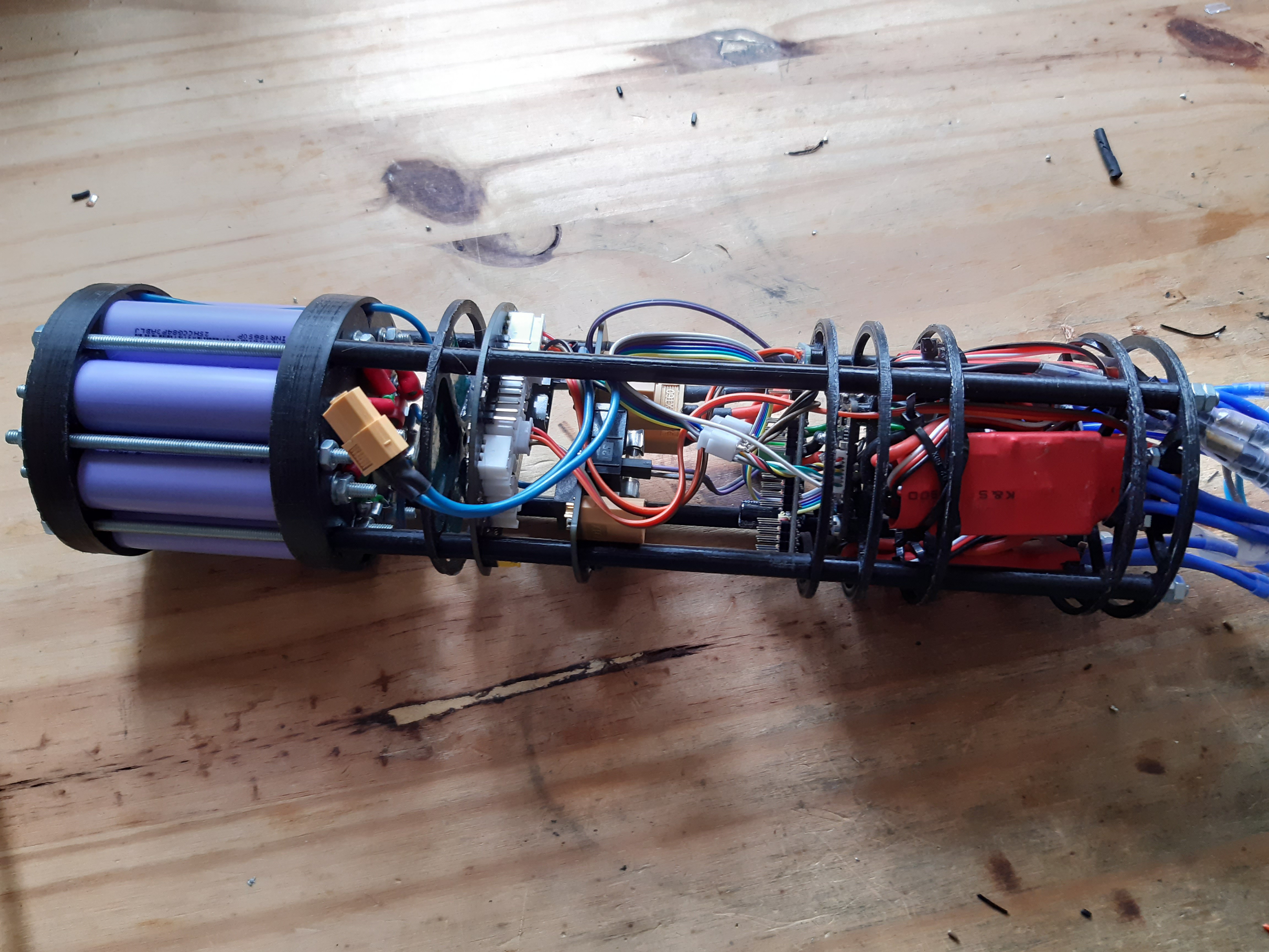
With everything working now the next step is to put everything together so it will fit into the tube again. Curiously the total size of the assembled core (I am going to call the electronics inside the tube core from now on in lag of a better word) is 3 cm larger than previously! I hypothesized that it would be smaller. But because of the extra space the XT60 cable takes around 4 cm is lost (notice the space between the power and the PCA9685 board). This is something I will have to reconsider in the next PCB design, because the PCB’s itself are very space aware the connections however, are not. I’m planning to put smaller side facing connections on the next iteration.
Discussions
Become a Hackaday.io Member
Create an account to leave a comment. Already have an account? Log In.