 Noeël Moeskops
New thruster layout design
The current thruster design of the ROV is quite agile with the 6 motors the submersible is able to move in 5 dimensions. With the front (1 and 2) en back (3 and 4) motors being able to use to go in 3 dimensions (X axis, Y axis and yaw). While the middle motors (5 and 6) can only make to ROV move in two dimensions (Z axis and roll). Still one dimension is lacking. With the current layout the ROV is unable to move in the pitch axis. This is not necessarily a huge problem as it is not required to move around but still would be nice to move in that axis.
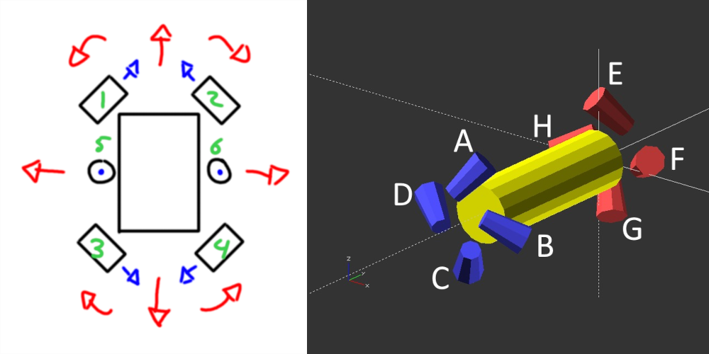
By adding two additional thrusters, and chancing to total layout the ROV can now move in all 6 dimensions. And it can do so with all 8 motors! Because all thrusters are located at a double 45-degree angle they are effective in all dimensions. They either need to move backwards of forwards. Four motors (A-D) are located at one end of the tube in a screw motion while at the other end the motors (E-H) are rotated in the opposite direction. This prevents the ROV from spinning around its own axis when all motors are active. The only downside to this design however is the cost in part and the power requirements. But regardless I think it is a worth it to build and try it out.
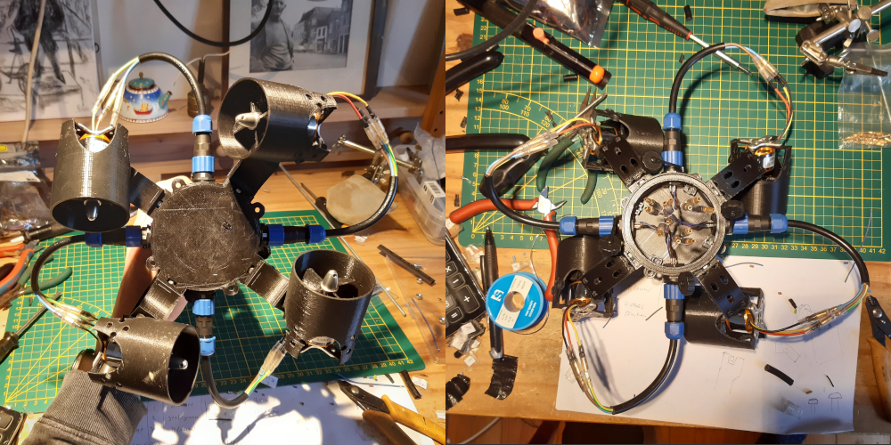
As can be seen from the pictures I constructed half of the new design. The motors are now intergraded into the end cap with SP13 connectors. But more on that in the next section.
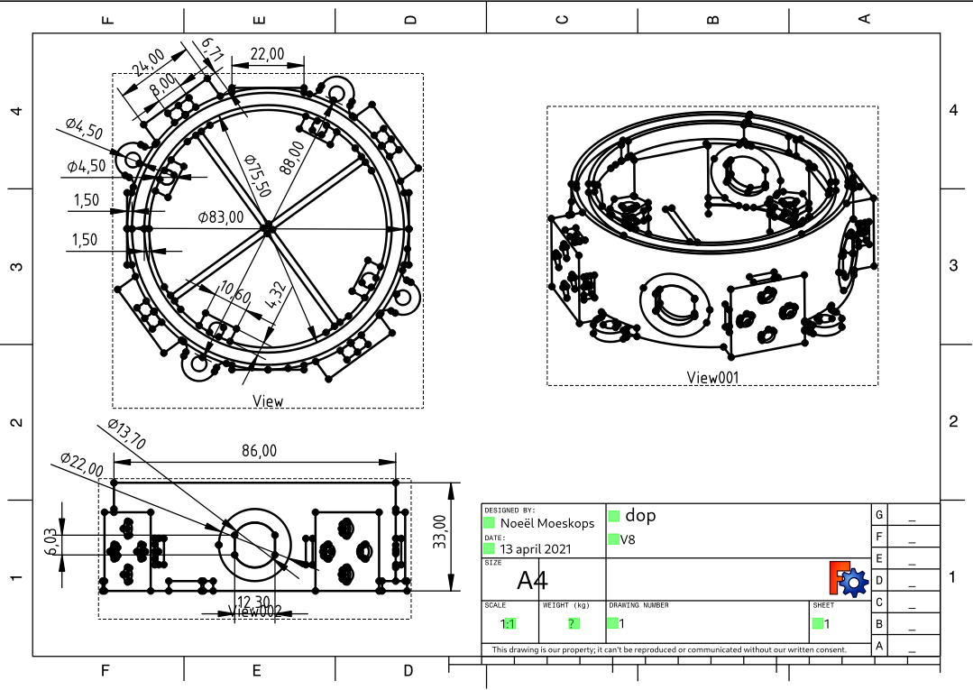
Cap
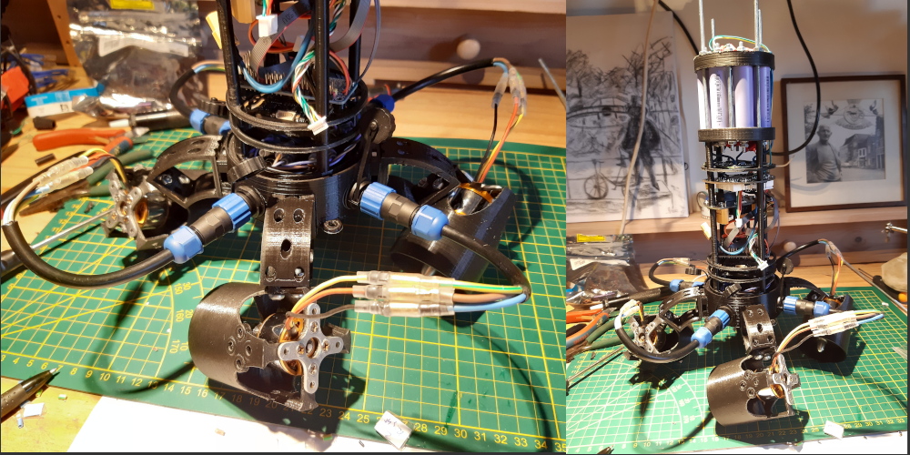
Another thing that really annoyed me was the cap of the ROV. The wires going inward where kitted to a strain relief and the solution was not very nice. The cap contacts the PVC pipe on side via two O-rings. This was not really a nice seal because there was no active force pushing the two together. It could in theory come loose mid-dive (what I was always really afraid of).
The new cap is designed to be forcefully pushed to
the PVC pipe by four m4 threads that are connected to the cap at the
other side. Between the cap and the PVC pipe is a rubber O-ring to
make a tight seal. The cap also houses support for IP68 SP13
connectors which replaces the hacked kitted strain relief. And are
much nicer all together because they can be reattached easily. The new cap is also integrated into the internals of the ROV. Where before they were two separate parts. Now the cap can be screwed into the other internal component by four m4 threads also.
BLDC motor controller
Apsu is currently driven by four SimonK motor controllers and four BLHeli controllers. The SimonK drive the motors in the front and back while the BLHeli provide control to the motors for upward and downwards motion. The SimonK controllers were chosen because at the time I did not know the existence of BLHeli. Now when I have had some experience with BLHeli I'm not liking that either. There is very little documentation available and the firmware (properly with good reasons) is written in assembly, so really hard to read. When I implemented Dshot in my project I remembered it being a big puzzle of figuring out how to protocol actually worked. And I had to put together multiple blog posts from various websites before I got a clear image of how to protocol worked and how to interface with it.
Now that I need more motors and thus more motor controllers I don’t really want to go back to BLHeli, not just because of the lag of documentation but also because the pins on my microcontroller are all in use and I don’t have room for a separate pin for each motor if I’m running eight simultaneously. I would also really like to get data like RPM of the motor which is possible with BLHeli but will cost an extra pin for each motor (or you can put multiple together on one input/play with mutexes etc. but that only makes your life harder). I would just really like to control my BLDC motors with an existing digital protocol like I²C, SPI or RS-485 or something similar. After a fair bit of searching it turns out that these “dream” IC exists in various forms. Among others TI and ST have some interesting IC that can be interfaced by either I²C or SPI and just need 6 external MOSFETS to function. I only need to design a PCB. I can then however design to my taste. So it can fit inside the 80 mm tube and have MT30 connectors for the BLDC motors instead of solder points like most motor drivers have.
From microcontroller to embedded Linux
In my last blog I talked about the strain on doing only one continuous thing and keeping too much to my original planning. And that I was going to take a little break from computer science and focus more on the mechanical and electrical aspects of the project. Well, if you have read the previous sections you can see the result of that work :). But lately when I started programming the ESP32 again I noticed that I really just don’t like the platform as a whole. Debugging and programming the chip can take several attempt with me getting frustrated and rebooting the chip en replugging it in a different USB port in the hopes that it will work next time. It really becomes just a strain to program the ESP, it's not fun anymore. I spend most of my “programming” time trying to interface with the ESP32 and attempting to get valuable debug information out of it, so I can see what's wrong with my code.
So I decided to stop working with the ESP32 and start
development on an embedded Linux processor instead. This way I can
run my code from my laptop (with a USB to I²C/SPI adapter) with the
comforts of proper debugging and quick compile and execute time.
And when everything works I simply flash it to an external CPU (with the help of Buildroot). This
also gives me much more freedom in choosing a processor. Because
before I was kinda vendor locked on the ESP32 with very little
variants to choice from. Now I plan to first make it all work on my
laptop with a USB-I²C/SPI adapter and then later choosing a
processor.
Discussions
Become a Hackaday.io Member
Create an account to leave a comment. Already have an account? Log In.