 Bharbour
It was important to me to make this board software compatible with the original 3 Axis project #Stepmotor Driver Board for TI Tiva Launchpad . The software for that project has been in use for a while and is pretty solid. Also, there is quite a bit of software in this project and I just did not feel like writing it again. When I brought the single axis board up, I was able to flash the software from the 3 axis controller into the new board and verify operation of all of the features on the new board immediately.

As part of this project, I duplicated the debug interface from the Launchpad board on a small, separate PCB that is connected to the target processor via a standard 10 pin 1.27mm JTAG/SWD cable. The debug processor from one of the Launchpad boards was desoldered and installed on the JTAG/SWD PCB along with a USB connector and power supervisor chip. This approach works well. The tool chain is configured for the specific eval board and works the same as the debug on the Launchpad board did. Because the original project was done several years ago, the version of the vendor tools is pretty old at this point. Replicating the hardware expected by the old tools simplified the development by not requiring changing tool chains.

The unpopulated J1 Connector in the upper left corner would be used to flash the processor on the board, but was not needed.
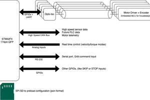
The end use for the board is to drive the Theta axis on my Antenna Rotator project #Satellite Antenna Rotator Mechanical System . Software support for the Theta axis is a problem because antenna rotators generally support Azimuth and Elevation only. The data protocol that I used as the input to the rotator control is based on the Ezcomm protocol, but it got extended quite a bit. Hamlib is an open source project that serves as a hardware abstraction layer between the top level control software and the various radio equipment. GPredict is the top level software package that I use to drive the Azimuth and Elevation axes to the predicted positions of the selected satellite. It has no understanding of the satellite rotational orientation, so it cannot command a Theta position for the earth antenna. By moving the Theta axis out of the AZ/EL command stream, it will be easier to deal with.
For testing, I created a manual control for the Theta axis position outside of the GPredict software. I extended the Ezcomm module in Hamlib to support the extra axis. This was not a graceful solution. Having the Theta control on a separate serial port and independent of the GPredict/Hamlib software will simplify this operation considerably. When I implemented the Theta axis control, I was expecting to write a tool that would control the Theta axis by optimizing the antenna orientation based on received signal strength. That is still to be implemented.
In the original system design, the Theta axis was driven from the 3 axis board via an exposed cable. As this is used for pointing an antenna, it is pretty sensitive to RF emissions. The original implementation radiated pretty severely when the Theta motor was enabled. Assuming that I can enclose the motor and wiring along with the controller board, the EMI problems from the Theta motor should be much lower. Additional input power filtering was added to the new motor board to reduce EMI on the input power wiring.
Hardware checkout and software development requires the debug interface, the target processor board and some implementation of the mechanical system.

The debug interface is shown on the far right, the Single Axis Motor Board is in the middle and a mock up of the mechanical system on the far left. A USB cable plugs into the connector at the bottom of the debug interface PCB to connect to the PC running the development tool chain. Power connections for the target...
Read more »


 plugg.ee Labs
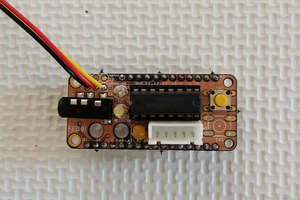
 Lex Kravitz
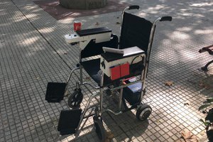
 Alvaro Ferrán Cifuentes
 anfroholic