 Dr. Cockroach
A rather dull test demo of the finished basic ALU full 4 bit adder.
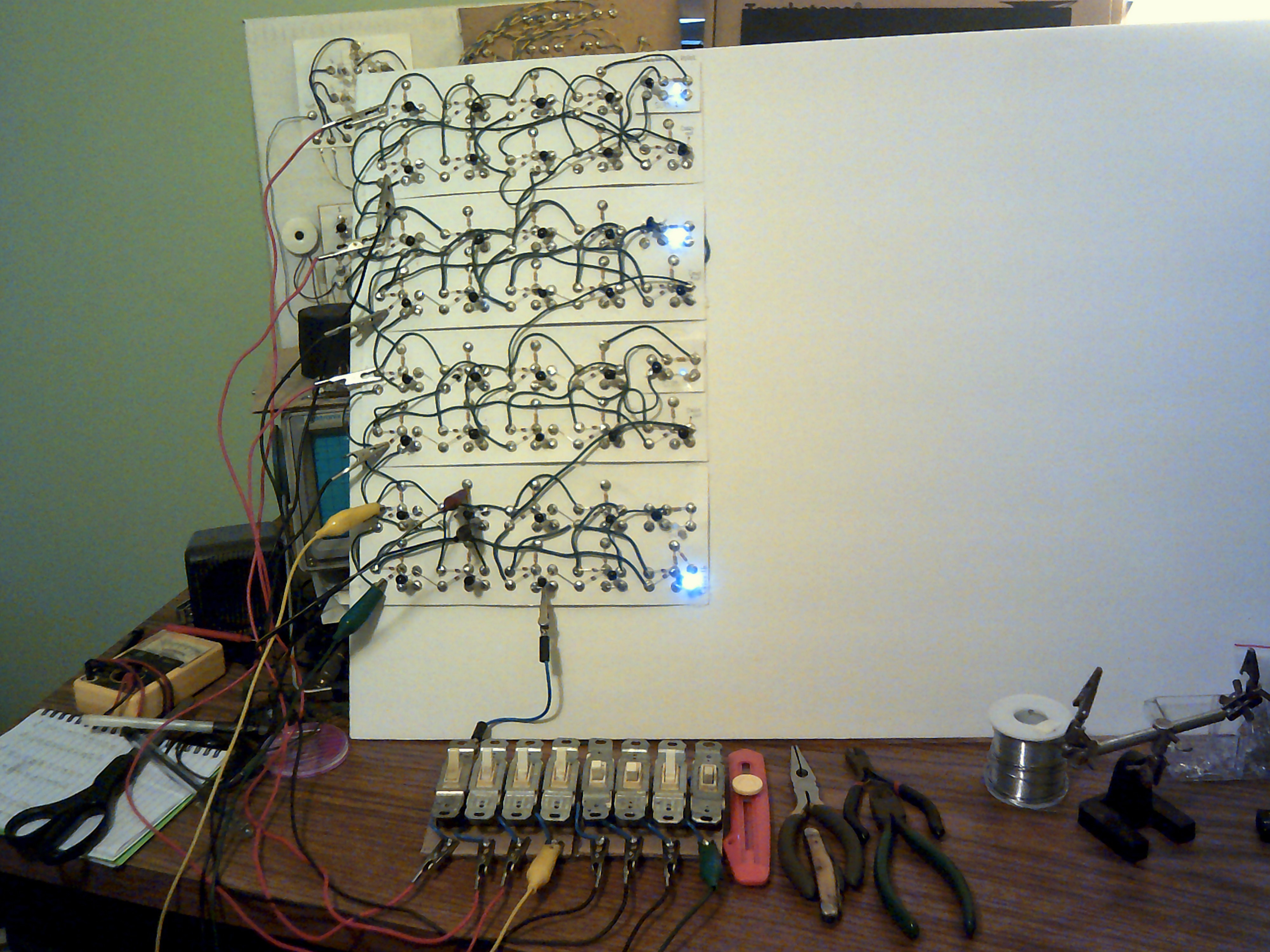
July 31, 2020 - The clip leads have been replaced but even this circuit with the input switch panel will change as the LLTP design advances. Next up is the Accumulator Register circuit.

July 28,2020 - Mounted the ALU/Adder to the first main panel and salvaged the input switches from IO. Next I will replace the clip leads with cables from the switches and the adder inputs. After that it will be time for the Accumulator Register.
July 26, 2020 - I just finished wiring the full four bit Adder/ALU and all inputs and outputs are working properly. For a better presentation I will add a input switch panel and mount the ALU to the processor master panel. First section of many.
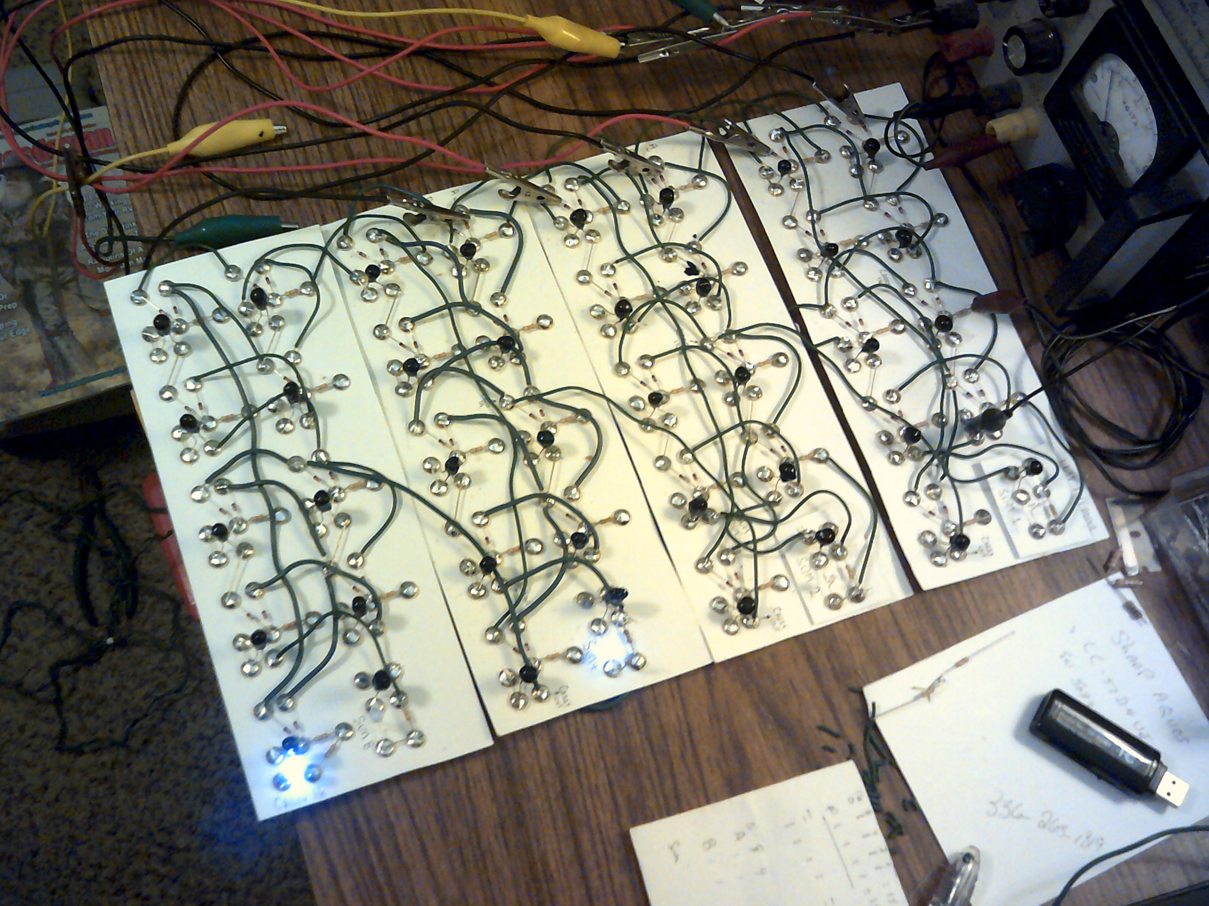
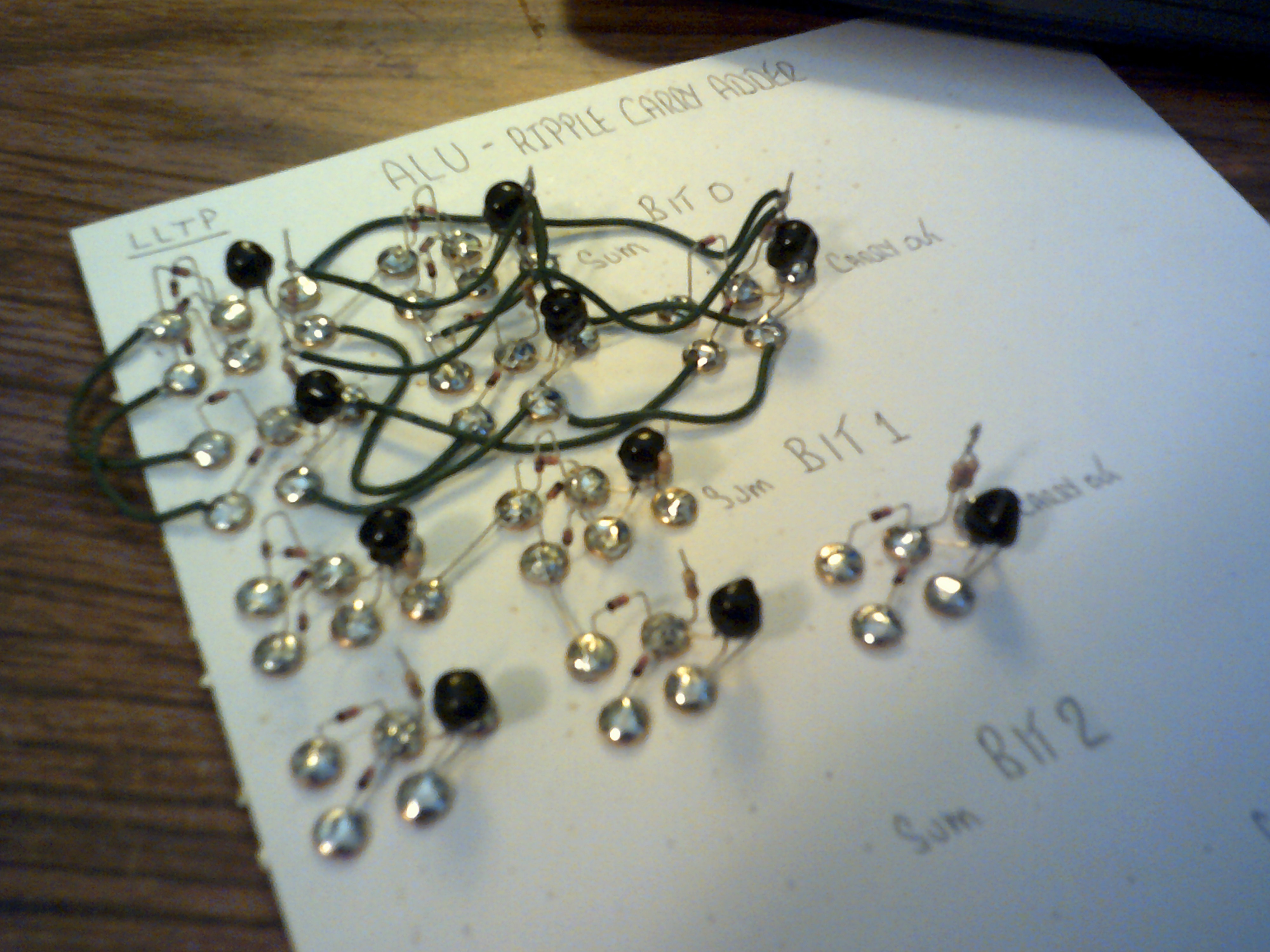
July 19, 2020 - Three bits of the adder are wired and interconnected. All inputs and outputs are working properly.

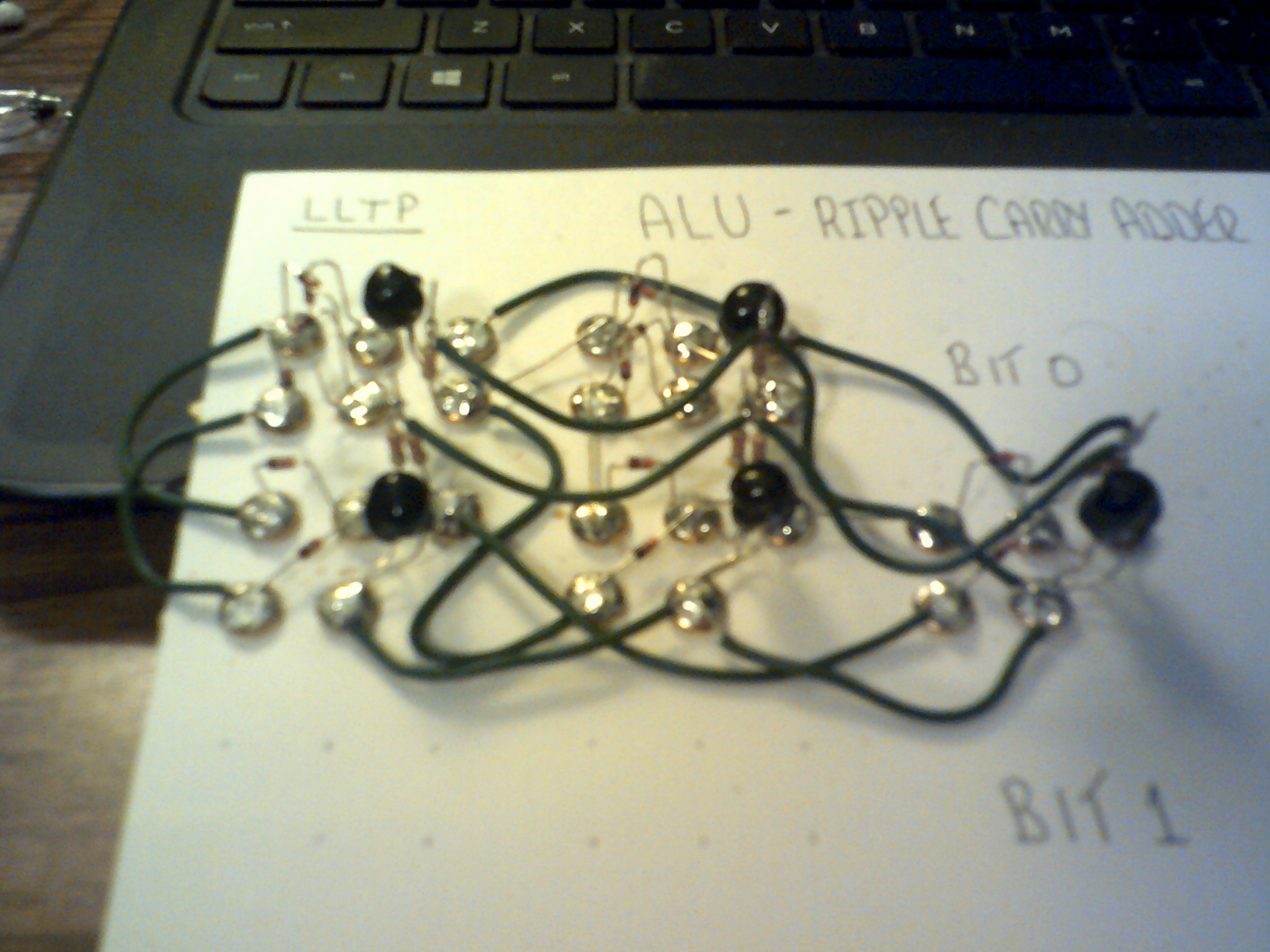
July 9, 2020 - Now have two bits of the adder wired and working. I have added a Not gate to each board as Led drivers for the Sum outputs and will finish connecting these next.
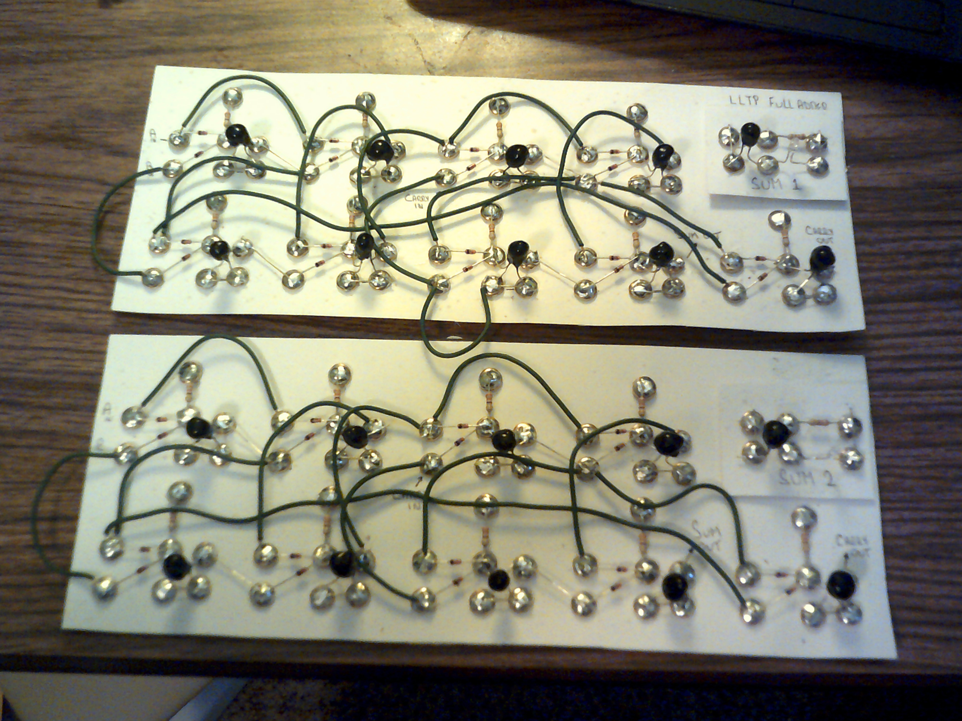
July 6, 2020 - Test of the full adder. Added two Not gates as Led drivers.
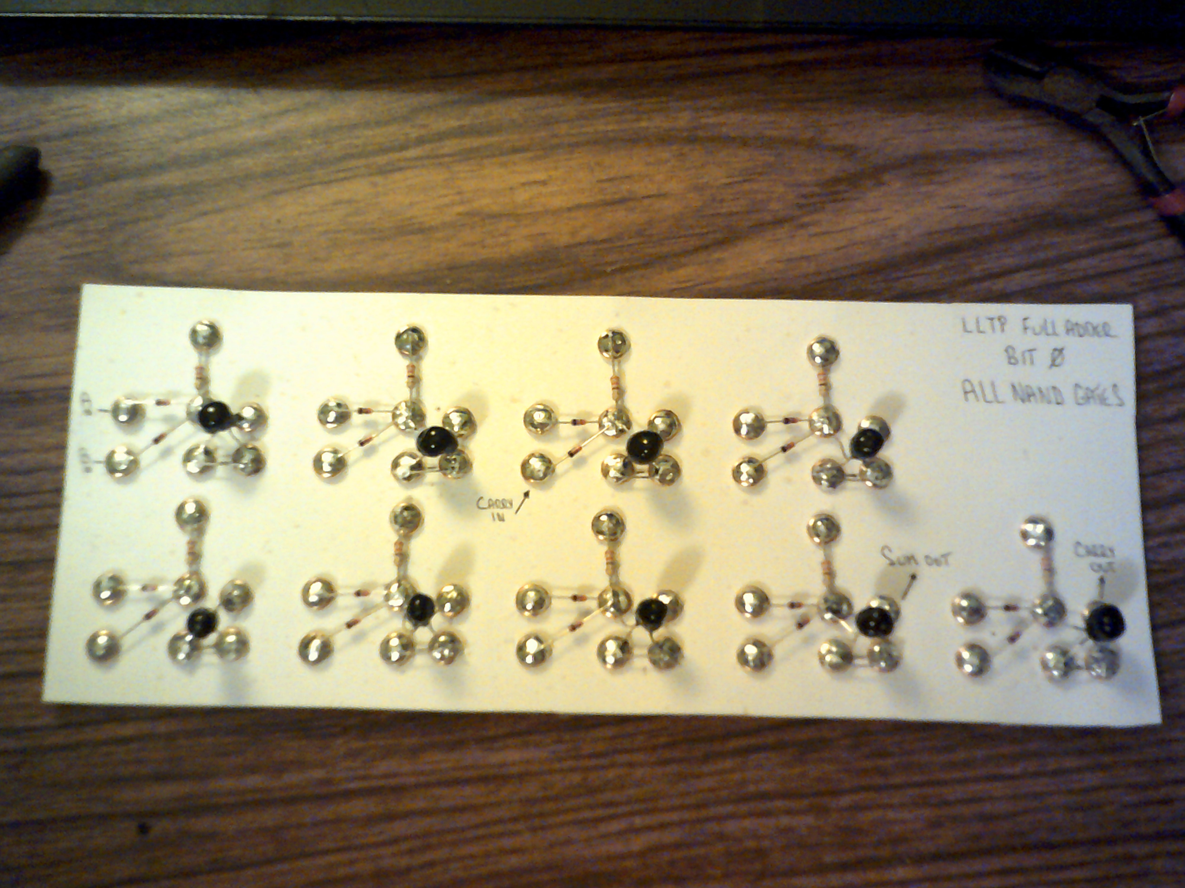
July 6, 2020 - First bit wired up with Nands and working like it should. Life is better with Nand gates ;-) I will post a short video of the test soon.
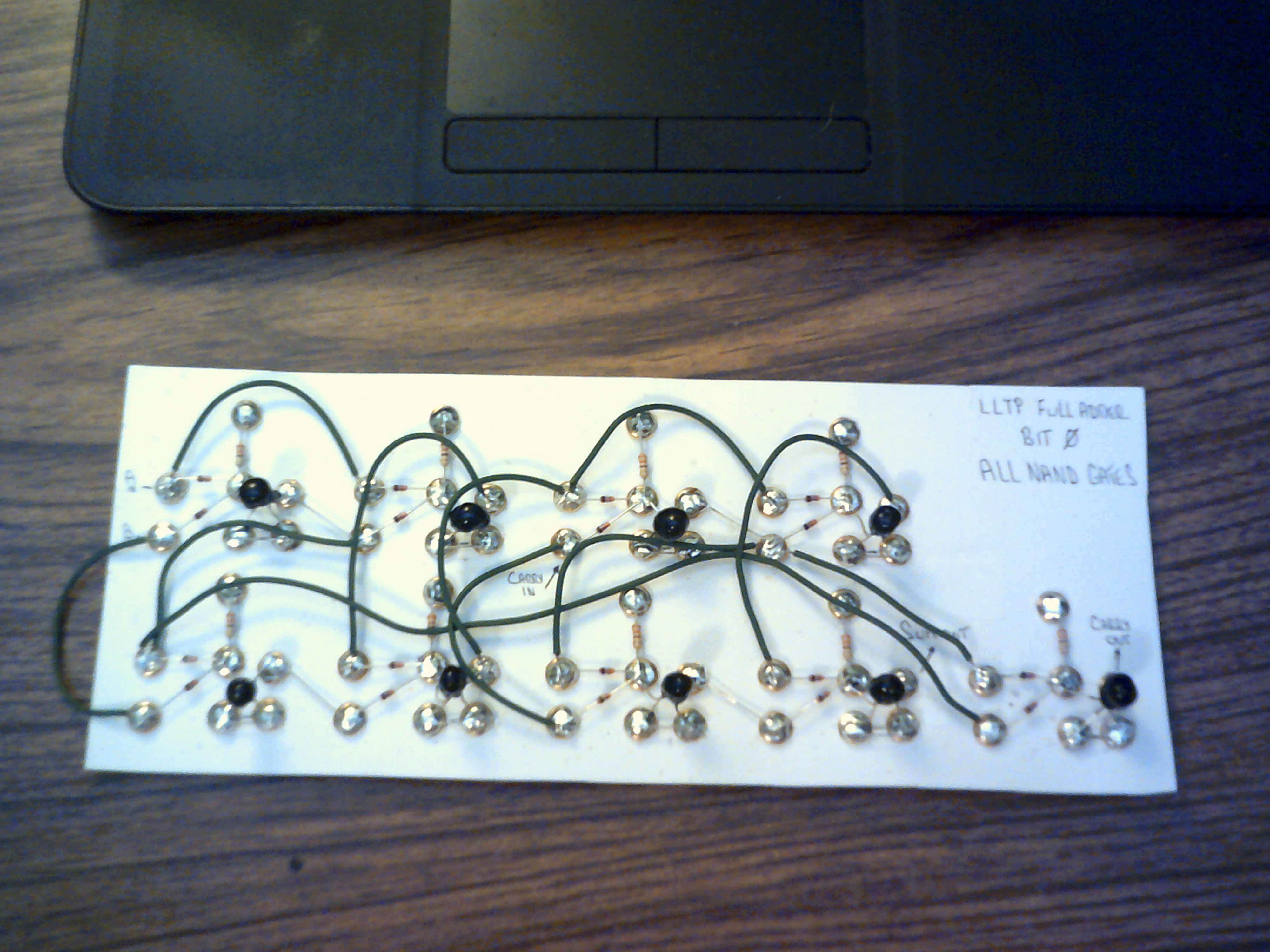
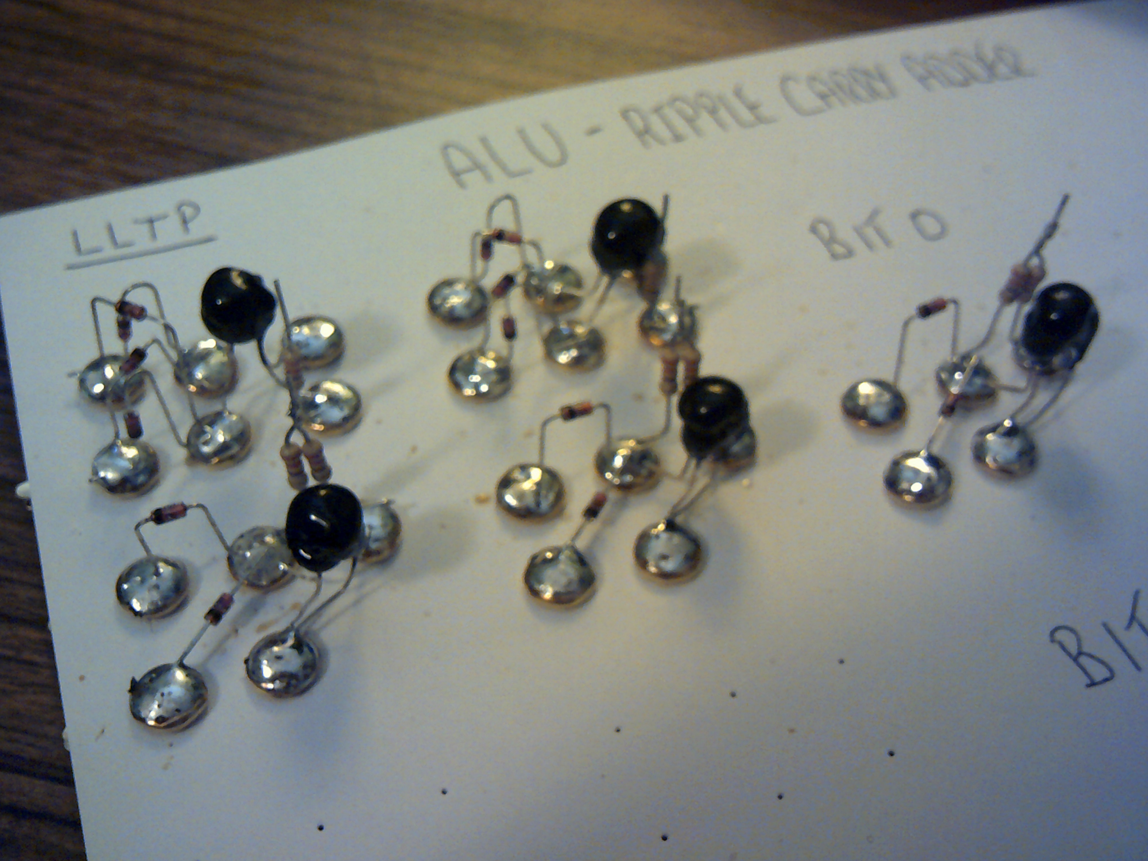
July 6, 2020 - The front of the first adder bit. All the Nand gates are in position, tested and ready for the logic wiring.
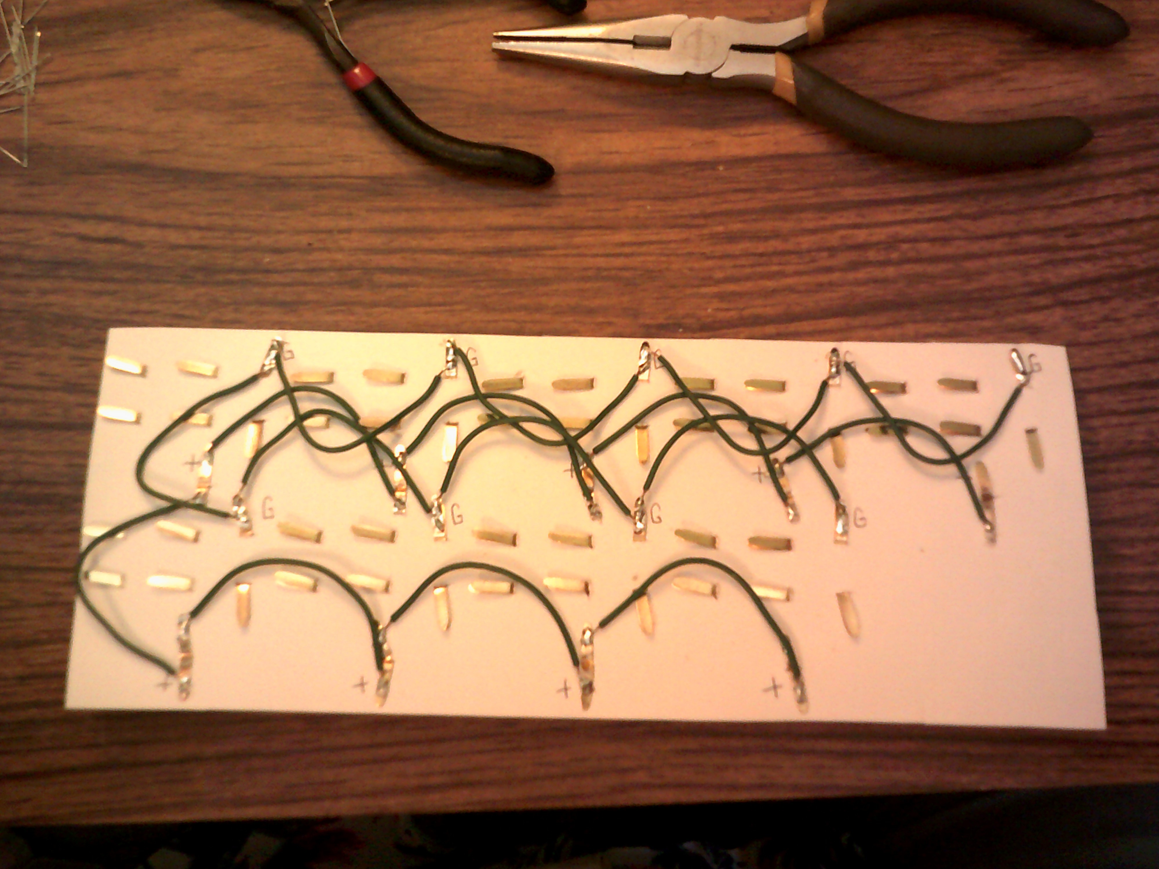
This is the power wiring on the back of the first adder bit. This helps make the front logic wiring easier to follow.
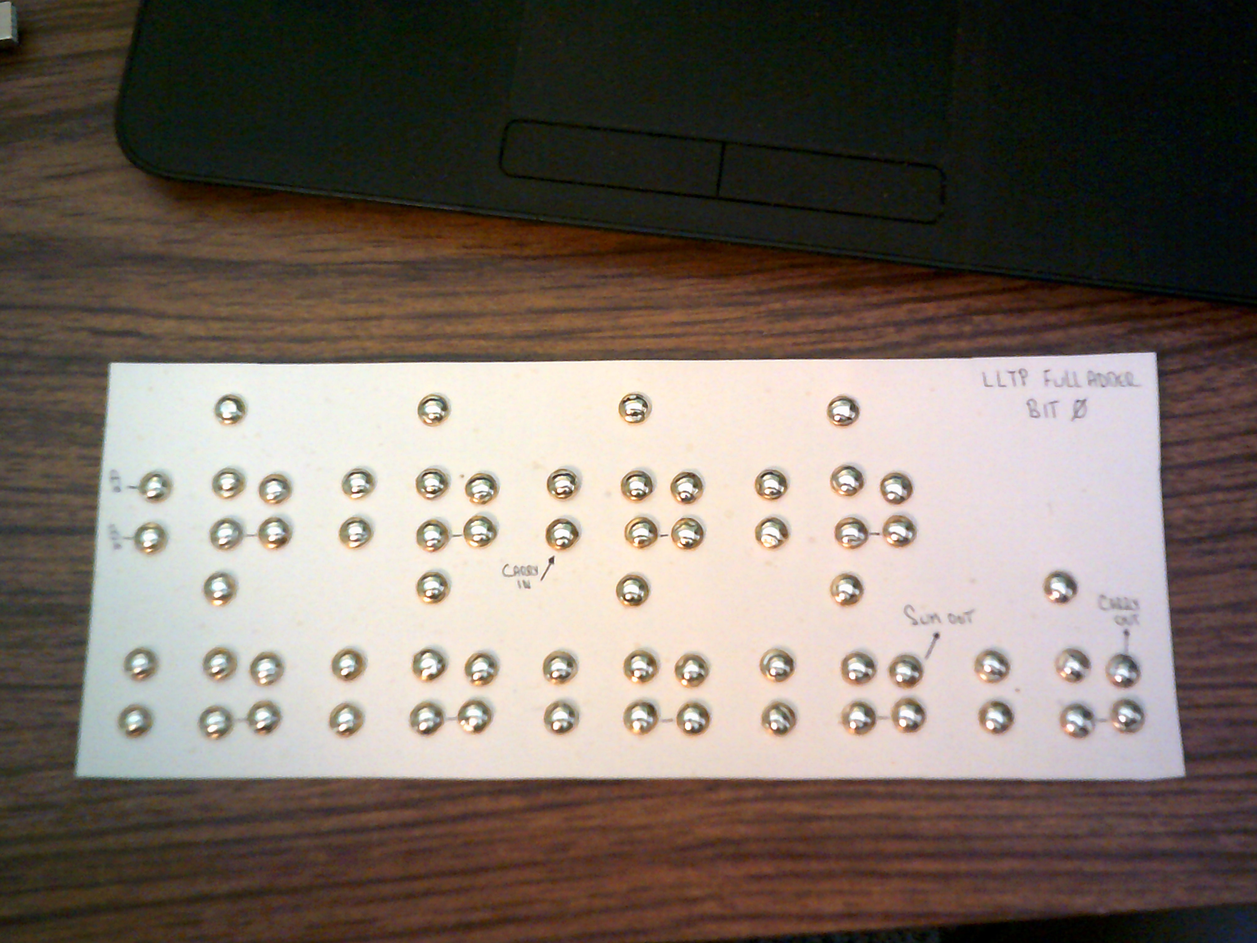
July 4th, 2020 - As per usual for my style of construction. Paper fasteners on card stock. This the layout for the nine required Nand gates for the first bit.
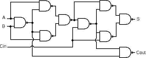
The typical accepted Nand logic for a full adder. Basic and easy to wire.
July 3, 2020 - Well, it was bound to happen. I had hoped that my stand alone Xor gate would save me a lot of gates and wiring but instead, due to logic level issues, was going to end up using more Light Logic gates than a pure Nand gate adder. So......... Starting over and going to just use Nand gates as I should have in the first place ;-)
June 21, 2020 - Bit 1 now has the diodes and resistors in place. Now to get the logic wiring finished up.
June 18,2020 - Here is the first ALU bit wired up. Sum and Carry outputs are working as expected.
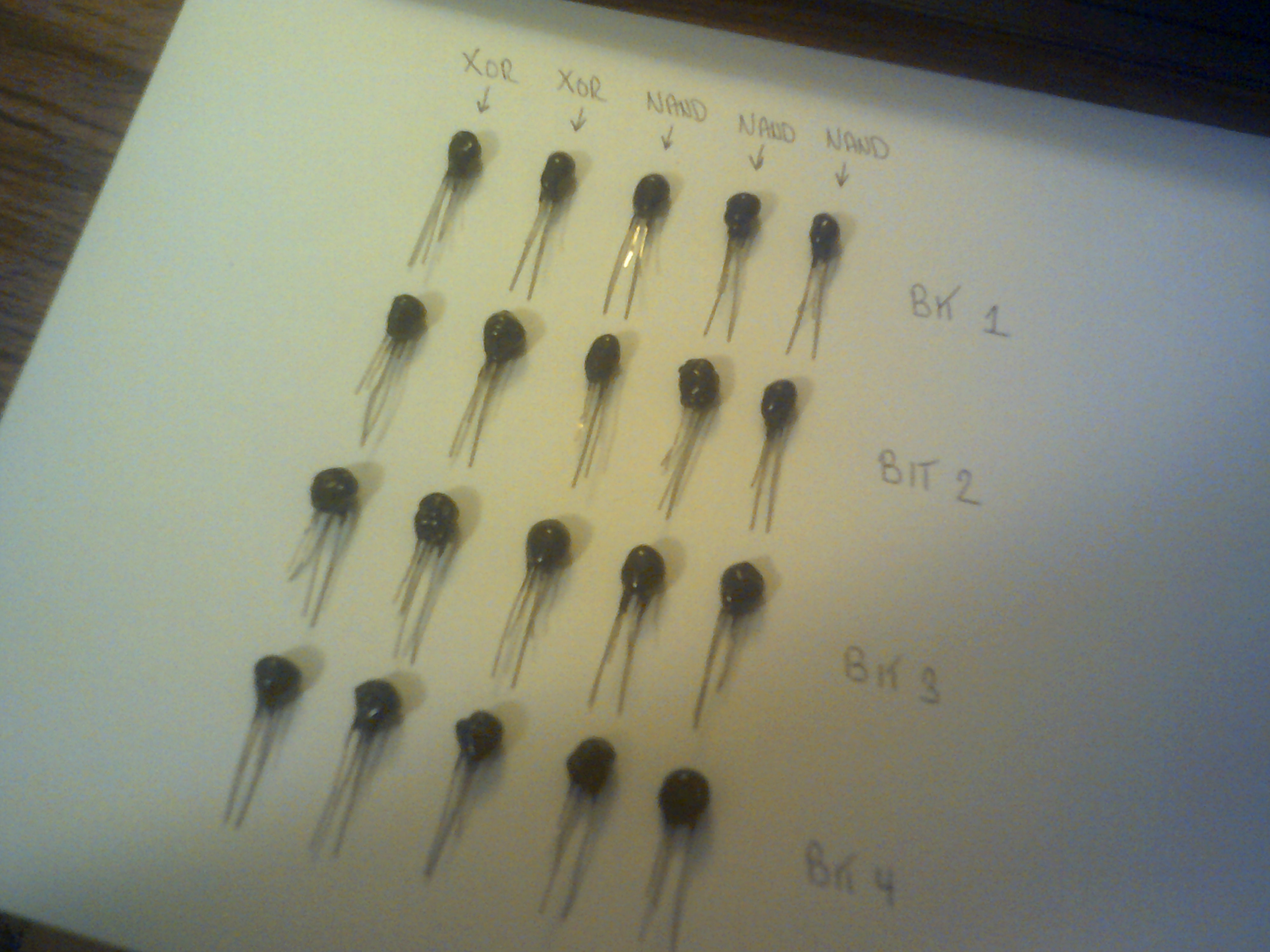
June 17, 2020 - This is the state of the ALU. Two Xor gates and three Nand gates are finished for bit zero and I just need to interconnect. Then comes a series of tests.
For the ripple carry adder I am just using a basic tried and true logic arrangement.
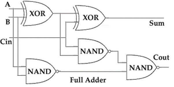
Just as I started IO the Cardboard Computer with learning to get a full adder working and understanding what went on in the logic, I will begin the LLTP with a four bit full adder. There are a lot of circuit images found on the WEB and this circuit will use the well tried and true 2 XOR and 3 NAND gate arrangement for each bit. I have just finished making the needed 20 Led/CdS pairs and the next step is laying out the parts placement and wire each bit one at a time and test. As usual, brass plated paper fasteners will be used on paper card stock.
Discussions
Become a Hackaday.io Member
Create an account to leave a comment. Already have an account? Log In.