I did initial testing with an Adafruit Adalogger M0 and standard 28BYJ-48 driver. The driver uses the ULN2003 darlington transistor array. I also tested out the ability to trigger the shutter on my Sony Nex-6 camera with an infrared LED. Although this worked, I didn't see the real need for camera control built in. Maybe if I build a future wirelessly controlled version I will add that, but for now it is easy enough to use the delayed shutter mode on the camera itself. Note that for astrophotography you want to ensure a delayed shutter so that pushing of the button doesn't shake the camera too much and ruin the photo. After proving this worked out, I designed a custom PCB for the driving. I decided to try out JLCPCB's assembly service and EasyEDA for this design, since it was so simple. I had previously used Macrofab's prototype assembly service, but they recently changed their focus away from that, vastly increasing their starting price. JLCPCB has a set of parts that they will assemble onto your board for a very low cost and fairly fast turnaround, but with strict limitations:
- All placed parts must be on one side
- Only parts in their library can be placed
- https://jlcpcb.com/parts
- Their search/filtering tools are unbelievably AWFUL, so it is quite difficult and time consuming to search through their parts listings
- They have no connectors supported. Even a standard USB micro would be incredibly useful, but alas. I used a strange vertical through-hole USB micro connector instead that I soldered by hand
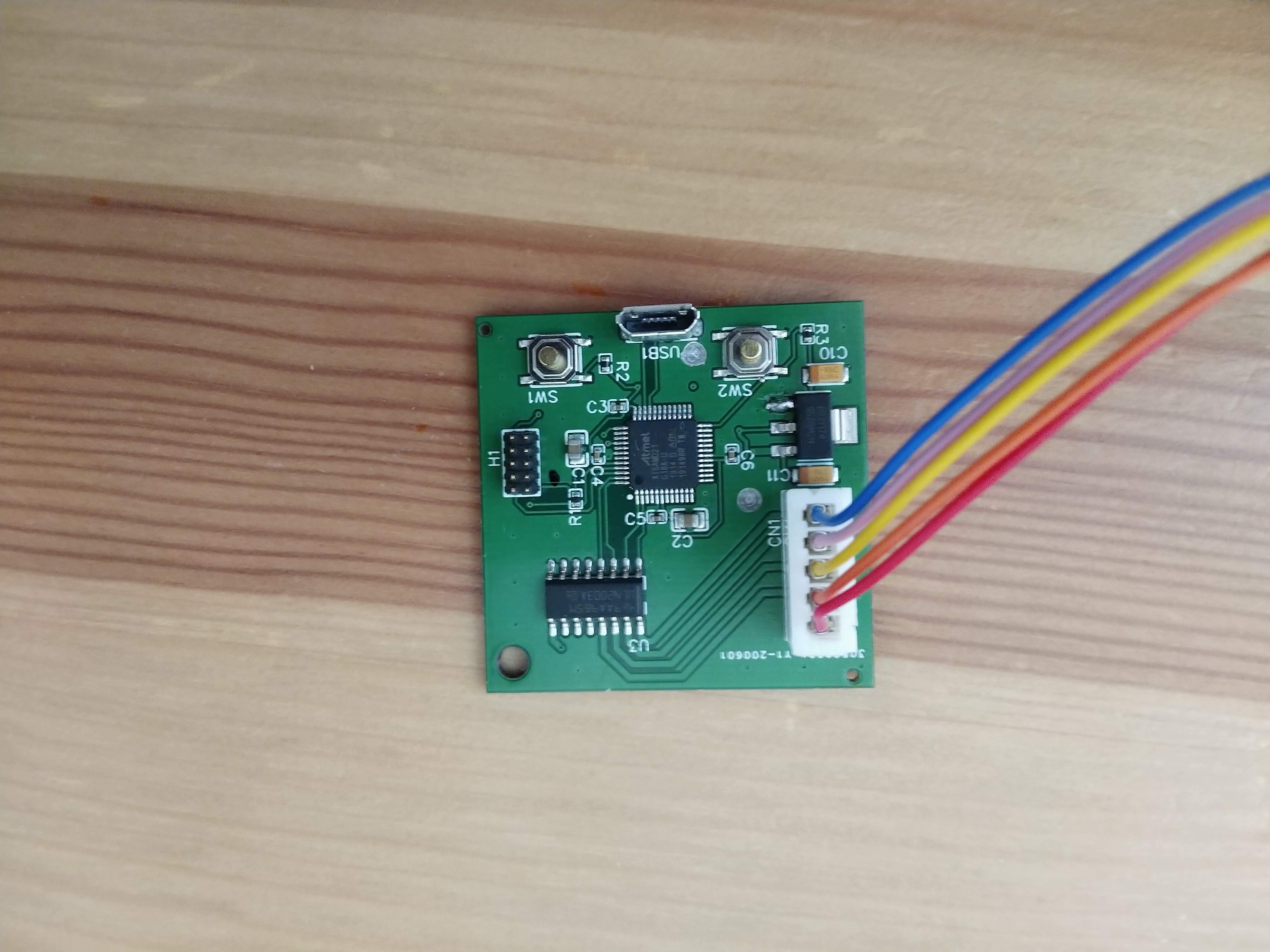
The boards are relatively simple, with a few main parts:
- USB micro for power
- ATSAMD21G18A microcontroller (way overkill, but available on JLCPCB)
- Standard cortex programmer header
- Two pushbuttons for control
- Strange-brand but very cheap LDO 3.3V regulator
- ULN2003A darlington transistor array
- B5B-XH-AM (LF)(SN) connector to stepper motor
The boards seem decent quality. However, I immediately noticed a major problem. Unlike Eagle, EasyEDA doesn't show the top and bottom layers partially transparent. Therefore, when I did some via stitching of the ground planes I accidentally put two vias between GND and the 5V input, shorting them together. Thankfully, I was able to drill them out on both sides to separate them. Note the two drilled spots on the board below.
The firmware for this system is simple. All we need is the ability to manually step the system in both directions, and the ability to change into a mode with will track a constant rotation rate. The only difficult part is the inverse kinematics to determine how many steps to drive and at what time to do that. I set the problem up as a tracking control problem with a simple proportional controller. The system has no position feedback, so it assumes it is properly set to be fully retracted upon boot. Over time, a desired angle is determined based on a constant rotation rate of 15 deg/s. The current position is calculated, and a certain number of steps are calculated and executed as below:
// Simple P controller
float current_angle_deg = calculate_current_angle_deg();
int32_t steps_to_move = (int32_t) -50.0 * (desired_angle_deg - current_angle_deg); // move out
step_motor(steps_to_move);
The remaining difficult part is to determine the current angle based on the number of steps. The stepper motor has internal gearing so that the number of steps per revolution is 2037.8864, and the M5 threaded rod has a 0.8mm pitch. Therefore, it is easy to calculate the linear motion per step, but that does not tell us angle directly. Due to the 3 hinges, the true equations are fairly complicated. For now, I am approximating it as a triangle and use the law of cosines to determine the current angle. Based on testing, I will see if this is good enough.
All of the firmware is on the Github linked to the project.
Finally, below is a time lapse, slowed by 32X of the system "tracking the stars." There is a bit of wobble due to misalignment of the threaded rod which may become an issue, but I will know better once I get a chance to test it.
Discussions
Become a Hackaday.io Member
Create an account to leave a comment. Already have an account? Log In.