 Sci
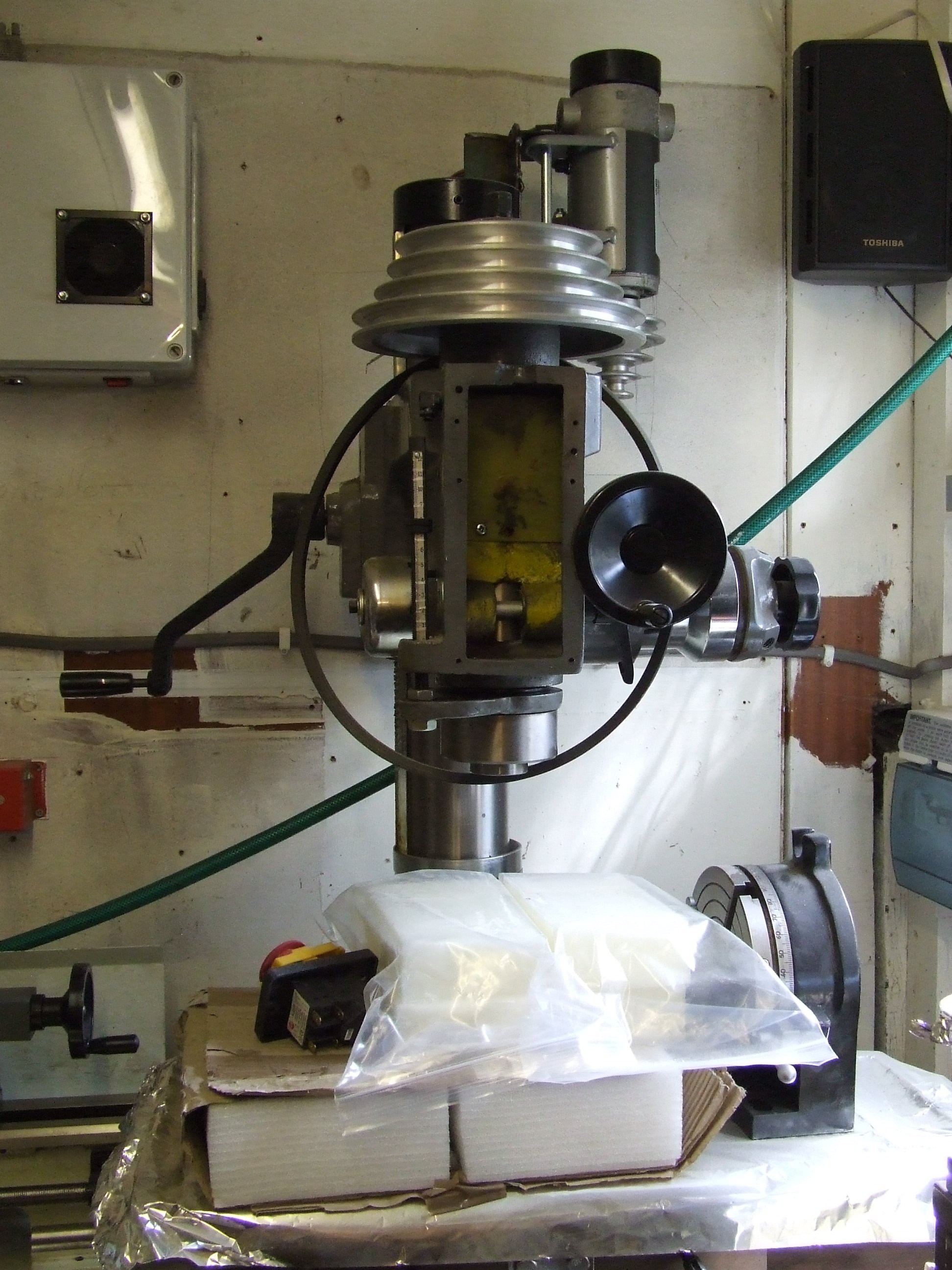
SciA while back I invested a good chunk of money in a nice big milling machine. Too big as it turned out. With the stock AC motor attatched it was too deep to fit on my workshop bench.
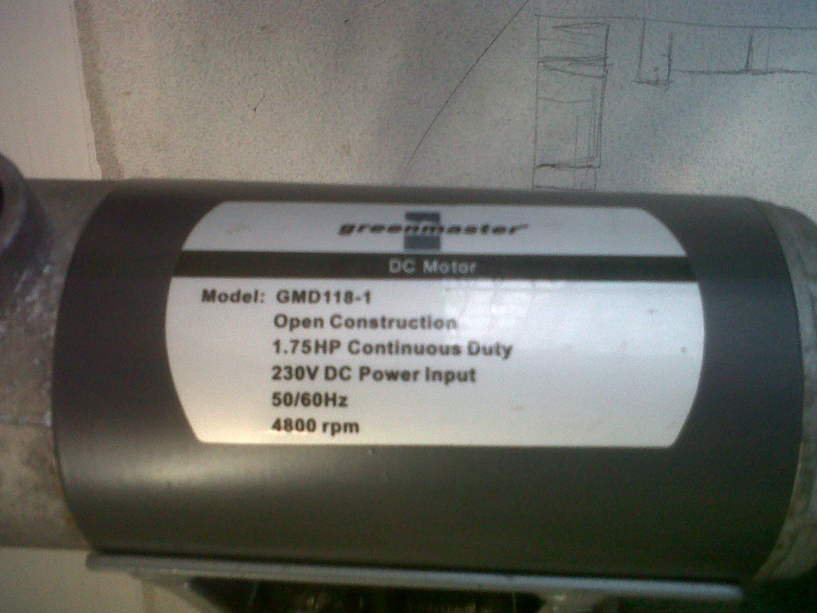
So I picked up a cheap wrecked treadmill, yanked the 1.75HP motor and made up a mount & pulley adaptor for it. It worked lovely.
Right up until the treadmill controller shorted out & nearly set the motor on fire.
The controller was a right-off, but I managed to salvage the motor after replacing the carbon brushes and skimming the commutator bars smooth on the lathe.
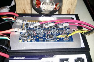
In this chaos though, an idea was born. To make a better controller. Safer and a lot more useful, that could be applied to similar DC motor tools.
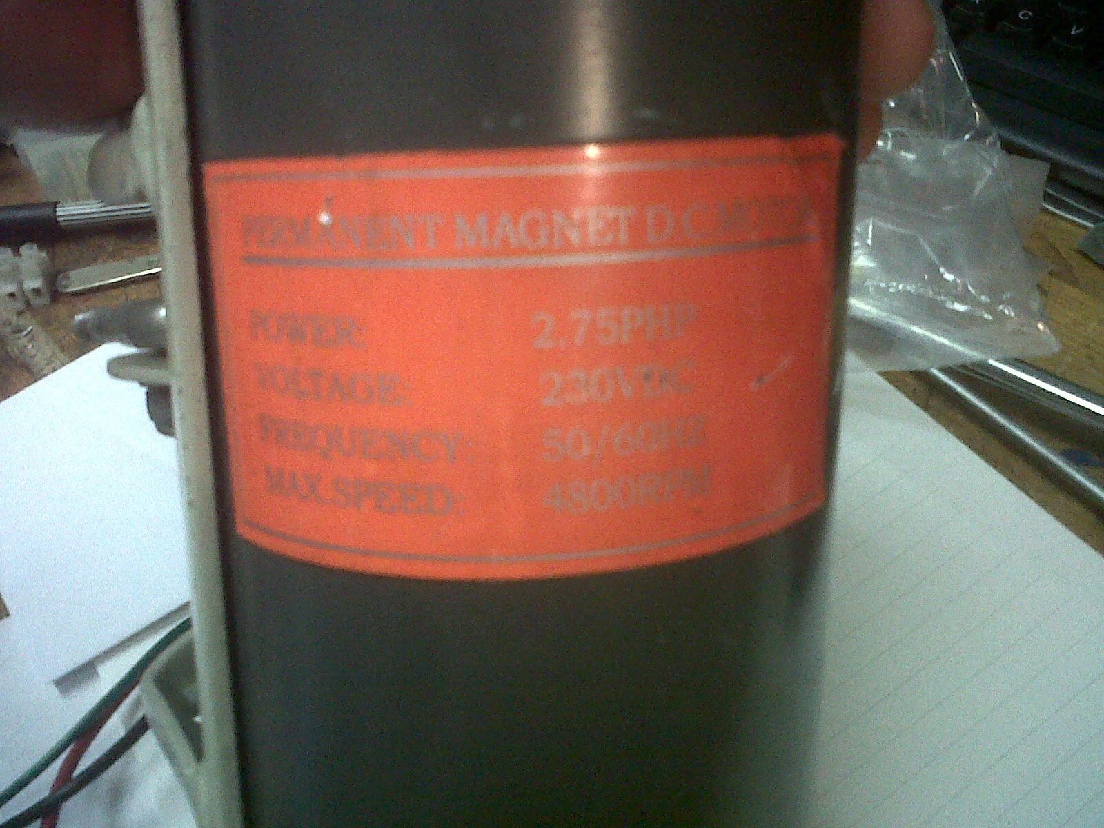
Turns out the most common voltage for these big DC motors is 230VDC in the UK. Problem is the peak-to-peak voltage of mains AC power is 370v. What I beleive the controller was doing was running the motor at a reduced PWM duty-cycle to give it the correct equivelent. Up until the controller shorted and jammed the control MOSFET on, dumping full rectified mains into the motor, sending it way past it's upper limits and spraying my workshop with sparks.
If I'm going to be using a big DC motor, I want it to be safe to start with. That means instead of using a reduced duty-cycle to make the motor think it's running at the right voltage, I'm actually going to use the right voltage then PWM regulate that.
While I have my own motors to think of first, I know the common Chinese import lathes and mini-mills tend to use 180VDC motors, and some American treadmills (favoured source of cheap 1-2HP DC motors) can apparently be as low as 80VDC. With that in mind, I'm looking at using a Power Factor Correcting buck-boost power supply and aiming to have the eventual PCB laid out in such a way to leave space for the motor-specific caps and inductor choices, whatever they may be.
Once the right power supply is done, it's onto the control. Simple PWM will handle speed control, but that control will be set by a microcontroller.
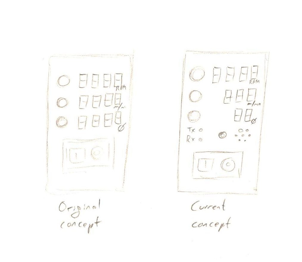
The current concept design has three 4-digit 7-segment displays, each with it's own rotary-encoder switch. Depending on which is used, you could set raw RPMs as usual, or dial in the cutter diameter and the ideal cutting speed for the material and have the controller automatically spin up to the correct RPMs for that setup.
But how will it know what PWM duty to use? You're still going to have a power transfer system from motor to spindle and it's probably not 1:1. Are you going to have to dial in the precise gear ratio of the machine?
No. Let's just have an RPM sensor on the spindle. A magnetic pickup maybe. When you first start it, go to calibration mode and let it run at, say, 10% speed. Shouldn't take too long to work out the ratio!
Overload protection is a case of poly-fuses, maybe with a current sensor for early-warning. Temperature is a thermocouple. Using the same theory to run a lathe just means altering the code to take diameter input from a DRO input (with upper limits of course! Can't run a lathe at infinite speed!).
No, it's probably not the biggest thing to happen to machine tools. Yes, you could probably do just fine without it. But cumulatively, I think it could make a big improvement in the quality and capacity of peoples home workshops.
That +5% efficiency multiplier in a game makes all the difference.


 Jarrod
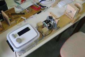
 shlonkin
 Jonathan Beri
 Joseph Eoff
Did you ever finish this project? BTW, Chester Machine Tools doesn't sell this model anymore.