 Sci
SciWhat I have to work with will define the initial build, so let's press on with that.
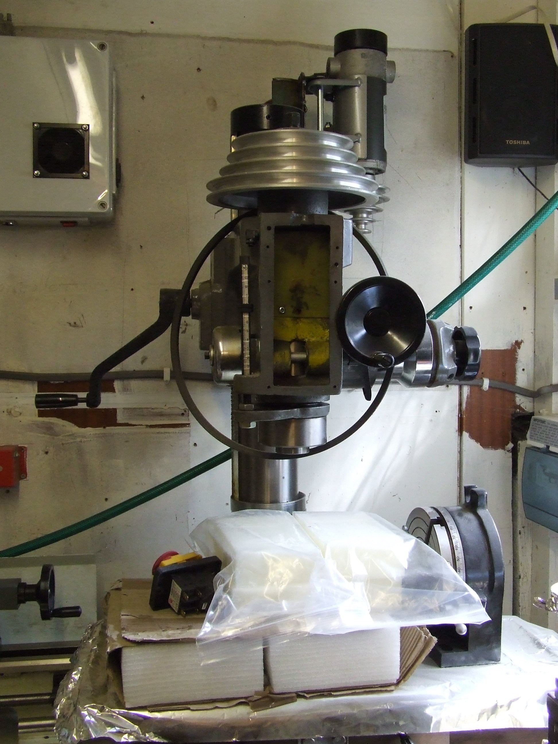
My mill is a Chester Machinetools Eagle 25. The standard induction motor is 3/4HP and the two-belt gearing set gives it a standard range of 100-2150rpm. I've already stripped it down though.
To fit the DC treadmill motor I fabricated a simple bracket to mount the treadmill belt-tensioning arm on. An aluminium bushing fits the motor pulley to the M12 treadmill spindle fitting. The positioning looks odd but works. With the middle pulley removed, the highest gear ratio is about 1.7:1, so the upper limit using a 4800rpm motor should be around the 2800rpm mark. The lower end will depend on the motors stall speed plus whatever feels like a good safety margin. At 5% it'll be about 240rpm at that ratio. The low-end belt ratio is about 1:7.69 though, so at 5% it'll give 31rpm. A potential improvement in range in both directions!
Auto-calibration will be nessesary any time the pulley ratio is changed. A POST operation is probably a good idea.
The motor in question comes from a Roger Black "Gold" treadmill the owner threw out because it "caught fire". Which meant it made a lot of smoke. This turned out to be from the plastic output pulley coming loose on it's shaft and rubbing against the running platform until it melted. The motor was fine.
The motor is a Greenmaster GMD118-1, and as you can see from the sticker it's spec is a bit odd. 230V DC. At 50/60Hz. Umm...
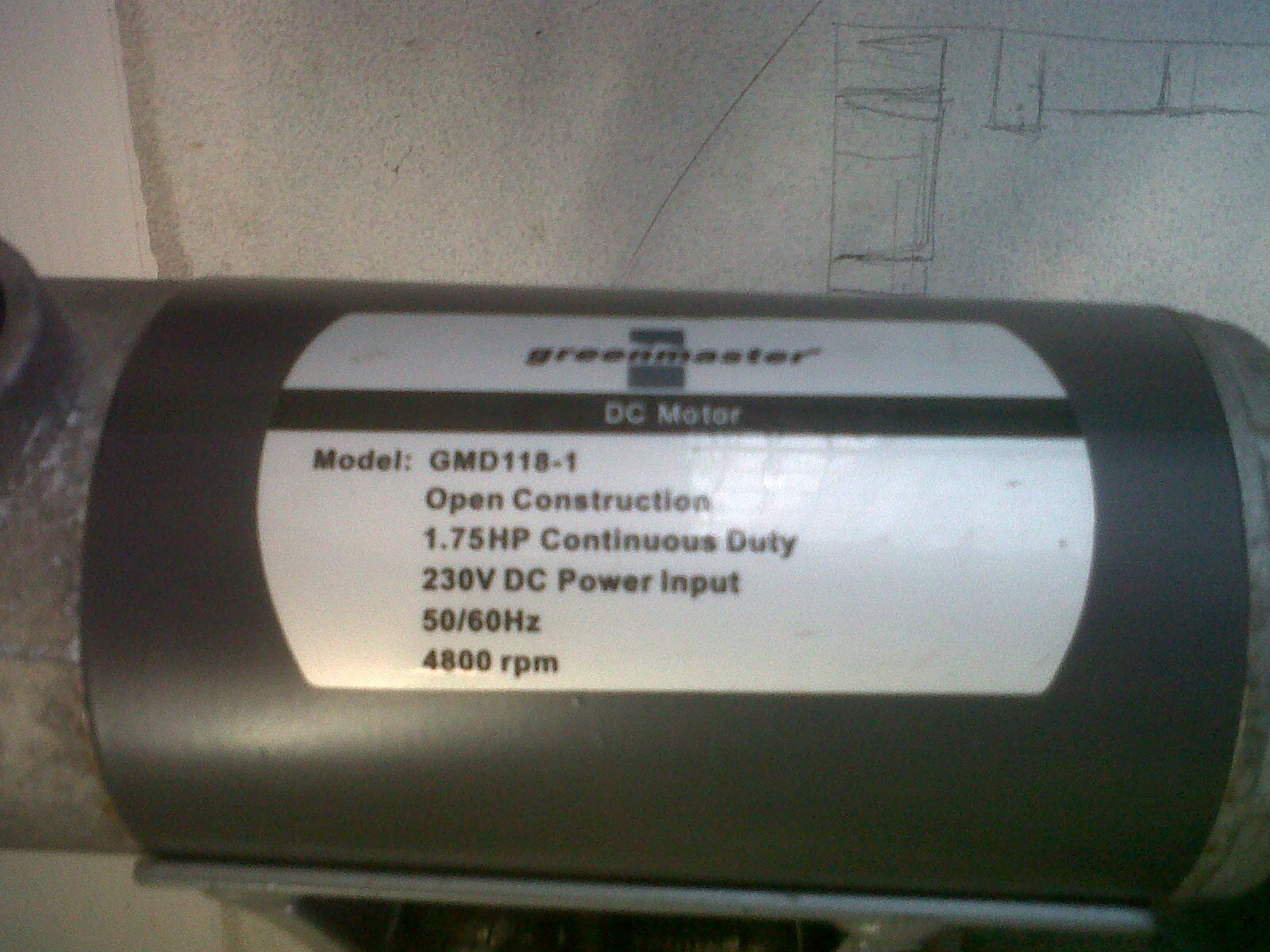
Shops selling them give them a "compatible" voltage range of 180-230v. It's one of the better brands but of still generic chinese DC motor stock, so I'm putting the AC frequency mentions down to bad translation.
Online shops also list the spec's as being 1.5HP and anywhere from 4000 to a crazy 5600rpm! On the old controller though 10% power put out 471rpm, so I'm inclined to beleive the motors own label. I'll still be very cautious running it up to full power in testing.
So, 230VDC is the aim. The cont. duty of 1.75HP comes out at around 1305Watts. However the apparent peak power I've seen on (physically identical) motors from other generic manufacterers has been 2.75HP, which comes in at 2050Watts.
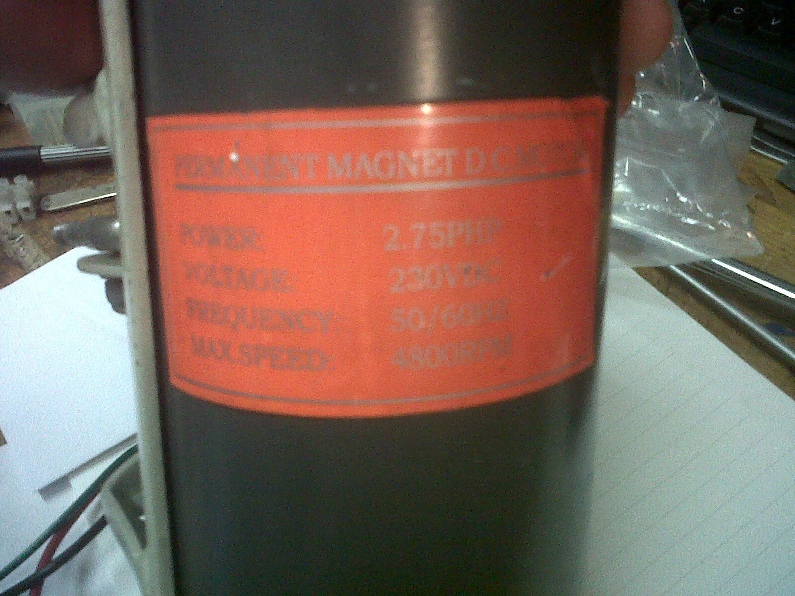
It's an important note to make that some treadmill motor manufacturers seem to list peak motor power and some list the continuous duty power in their specs without defining which it is. Watch out for this when sourcing your own treadmill motors.
The current sensing is going to come in very handy for testing the motor specs against reality.
To accomodate the gulf of mystery, the initial build is going to be spec'd for a 2Kw power supply.
I'm looking to use the Texas Intruments UCC28019. I'll freely admit I don't know a terrible amount about PFC controllers, but I was recommended this one and it's power and voltage specs seem to be suitable.
The example circuit design for it in the datasheet relies on their design calculator spreadsheet, which is very thorough but only has settings for boost converter configurations. To take rectified UK mains and drop it to 230VDC it would need to be a buck converter. Or, to allow the circuit to operate on a wider range of inputs and outputs, it would need to be a buck-boost converter.
TI's Power Stage Designer tool takes care of providing the specs for the major power componants (Inductor, diode, MOSFET) for a variety of configurations. The UCC28019's configuration options will need to be calculated from the datasheet formulea.
Of course the fact that they need individual configuration too means a universal PCB is probably off the table, at least until I've tested the waters some more. The path of least resistance to a working prototype is a buck-converter, so let's get that calculated next.
Discussions
Become a Hackaday.io Member
Create an account to leave a comment. Already have an account? Log In.