 Sci
SciA concept is a thing of sublime fantasy. It is a dream with no flaws. Reality isn't like that, so when you start to bring it to life, you start having to make changes to get it to work.
The control panel
The original idea was simple; three rows of 4-digit 8-segment displays, each row with a matching 2-bit greycode dial. Easy as pie until you start counting available pins on the microcontroller. I have some Atmega168's left over from another project, so we're going to try for a pure Arduino core.
I want to keep the parts count and cost down, so while I could use a multiplexer and a dedicated 8-segment driver, the segment drivers are about 5 times the cost of the Atmega. Plus if I use a dedicated driver, while I only need 4 lines to drive it, I only get the hex digit range at best.
I'd rather have complete control over what the display shows, as it would allow the display of error codes.
So what's the spec? Fantasy says twelve 8-segment displays, total. If you multiplex the display selector with a 4-to-16 line decoder, that's still 12 (8+4) output pins taken up right away. There's still 9 input pins required for the greycode switches (2-bit + button). So we're at 21 pins required and haven't even talked about the current sensor, MOSFET PWM, sounder, serial data, or RPM sensors.
The Atmega168 only has 28 pins, and they're not all usable. So let's start paring it down.
Do I need 8-segments? The decimal point is only of conceivable use for tool sizes, but throwing some imaginary numbers at the RPM formulae ( (m/min * 318.057)/dia ) says the mill won't be capable of reaching the speeds where fractions of a millimetre between tooling size are noted. A 1mm tool at 15m/min cutting speed (very slow) needs a speed of 4770rpm.
Practical considerations. You're never going to be using a tool that fine in a machine this big. We can forget the decimal points and go with whole numbers only without loosing anything.
One pin down.
Cutting speed examples (http://en.wikipedia.org/wiki/Speeds_and_feeds#Cutting_speed) range from a low of 15 up to 210m/min. (Thought I suspect machining waxes would be best with high, I can't find any cutting speed numbers for them, only RPMs)
In any case the cutting speed display only needs 3 digits. And if we limit the tool diameter to a very generous 99mm, then we only need 9 digits total.
So 7 pins for the displays and 9 to multiplex them. Still a bit hight. So let's get the 4-to-16 line decoder back in play. We can have all the original displays at this point if we like, but let's save costs where we can.
And you know what? Here's another saving. The multiplexing's happening faster than we can see, so our clumsy monkey fingers aren't going to outrun it. Let's turn the greycoder buttons into a 3x3 matrix and run the inputs from the end of the same decoder.
So now that's 7+4 outputs and 3 inputs to cover all the displays and manual controls. Much better!
It means using some of what are usually considered the analogue input pins as general IO, but the datasheet says it's fine. It also means there are sufficient pins left for the other functions. The standard serial pins are there, current gets an analogue input, MOSFET control gets a PWM pin, RPM sensor gets a digital input and we even have one PWM left for a small alert sounder!
I think that uses up every single pin, only requiring the addition of one cheap line decoder IC. Like a glove!
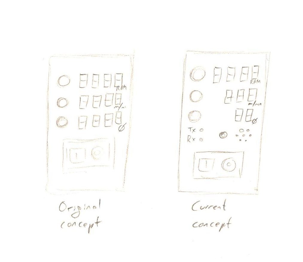
I'm still favouring a classic look with red 7-segment displays showing through a translucent black plastic fascia, laser engraved with the various labels.
Interfacing
Now let's start with something close to my wallet. However you cut it I'm going to be hooking a microcontroller up to a 9A mains supply and frequently modifying the code from my computer.
Every time I get something wrong, I do not want to have to replace my computer because the USB port took a 230v hit.
I looked up off-the-shelf possibilities for isolation of the USB connection, in case something goes wrong. Turns out USB isolators are very expensive. £40 upward for a unit, £10 for just the chip (ADuM4160 ).
I did a lot of window shopping before I remembered that what's coming off the Atmel chip is serial that goes through a serial-to-USB conversion. And serial is something I could handle with simple (and cheap) opto-isolation, so I'll just put the isolation before the USB conversion, not after. The serial-USB conversion can be powered off the USB interface, or sit dormant if unused. My computer should be safe.
Preventing disembowelment
This circuit is going to be driving a big, powerful motor. I'd rather it didn't power up at random.
As I know from running servos from my Arduino though, the pins of the chip can output erratically for a couple of seconds when it's first powered on. Maybe this is a servo-only thing? I'd rather not risk it. I need a way to ensure the motor's not able to run until the Atmega's had time to fully boot. I don't want a 2HP motor sputtering and twitching at random.
I'm thinking a simple latch circuit tied to one of the bidirectional pins that's input under normal operation. Once it boots, hold the pin as an output to charge a small capacitor that triggers a latch, and that latch enables the schmitt trigger. Tie it to the Atmega's reset pin so if it's reset, the latch resets too. Once it's booted and enabled, the pin gets changed back to normal duty. It's just a matter of getting the timing delay on the latch set right to clear all startup jitters.
Enabling safety
The emergency-stop is another concern. The usual no-volt latching stop-start switches are rated for AC mains. Putting it between the mains and the PSU though means there's a filter capacitor that's still able to power the motor briefly after the mains is shut off.
There may be a couple of ways of handling this.
Some variations of the no-volt switches have an additional “remote reset” pin. Depending on how they are wired internally, it may be possible to tap this pin to watch for no-volt states.
More realistically though, the switches come in three-phase versions, some of which are 3-phase at monophase voltages. A bit odd, but if they can be affordably sourced, the redundant third switched line could act to disconnect the motor power line.
This is the most shaky part of the design right now, as I'm finding it hard to determine how the reset lines on these switches are supposed to be wired, and where some of the feature combinations can be purchased from without costing more than all the other parts combined.
The PSU
I've been doing my research and so far I haven't seen any obvious reason why the PFC chip couldn't be used in a buck configuration rather than a boost.
My inclination is to just try it and see. I'm not sure the budget will stretch to producing a half-bridge rectified boost version as well as the buck.
If the buck PSU doesn't work, I may temporarily have to resort to the treadmill-method of a software limited PWM range to keep the apparent power level in check.
Discussions
Become a Hackaday.io Member
Create an account to leave a comment. Already have an account? Log In.