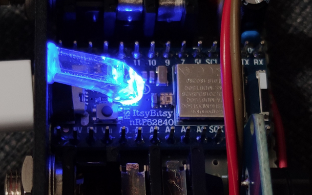
The circuit is very simple, basically two 1/4 TRS jacks connected to an Adafruit itsybitsy nRF52840 board (my new favourite arduino board).
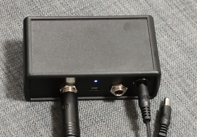
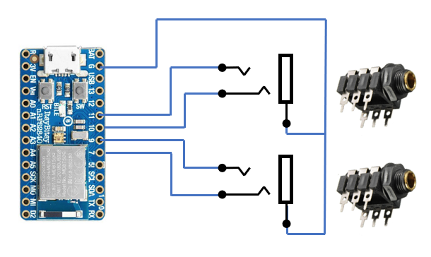 Each of these TRS jacks can be plugged into a BOSS FS-6 pedal using standard 1/4" TRS (Stereo) cable. Alternatively with the right stereo to dual mono cable splitter it should also be possible to connect two Boss FS-5U pedals to each jack. This gives support for a total of four pedal switches.
The code implements 3 modes, which can be switched between by holding down pedal 1&2 (A&B on first BOSS FS-6) for 3 seconds. The mode will change between 1-2-3 each 3rd second, and the current mode is indicated by the LED blinking 1,2 or 3 times.
The keypresses to be sent for the three different modes are defined in two two-dimensional arrays called keyPresses and modifiers. Each line correspond to each mode, and the 4 key presses corresponds to pedal A,B,C & D (BOSS pedal number 1 A & B = A & B, Boss pedal number 2 A & B = C & D)
uint8_t keyPresses[3][4] =  // Keypress codes
{
  {HID_KEY_PAGE_UP,   HID_KEY_PAGE_DOWN,HID_KEY_HOME,   HID_KEY_END},        // Mode 0 (Page Turner)
  {HID_KEY_R,         HID_KEY_SPACE,    HID_KEY_NONE,   HID_KEY_RETURN},     // Mode 1 (Garage Band)
  {HID_KEY_F9,        HID_KEY_SPACE,    HID_KEY_SPACE,  HID_KEY_HOME},       // Mode 2 (Ableton Live)
};
uint8_t modifiers[3][4] =   // Keyboard modifiers
{
  {HID_KEY_NONE,      HID_KEY_NONE,     HID_KEY_NONE,       HID_KEY_NONE},   // Mode 0 (Page Turner)
  {HID_KEY_NONE,      HID_KEY_NONE,     HID_KEY_NONE,       HID_KEY_NONE},   // Mode 1 (Garage Band)
  {HID_KEY_NONE,      HID_KEY_NONE,     HID_KEY_SHIFT_LEFT, HID_KEY_NONE},   // Mode 2 (Ableton Live)
};
The HID key definitions can be found e.g. here: https://github.com/adafruit/Adafruit_Learning_System_Guides/blob/master/Joy_of_Arcada/keys.h
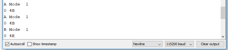
The code also prints out debug information to the serial monitor at 115200 baud. The button (A-D) and the mode number is displayed on first line, the HEX code for the Modifier and the key on second line.
The code also implements control signal for an optional active buzzer (active high, i.e. only a steady high level needed to buzz) connected to pin 12, which indicates mode selection with same pattern as the LED blinks:
1 blink/buzz: Page Turner mode
2 blinks/buzzes: Garage Band Mode
3 blinks/buzzes: Ableton Live Mode
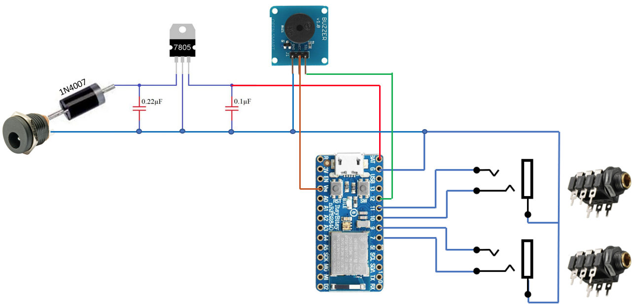
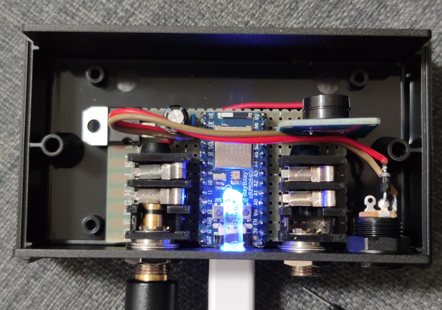
Adding encapsulation, buzzer and power supply.
I found the 1593VBK from Hammond Manufacturing to be a perfect enclosure for this project. To enable the board to be powered both over USB and 9V I added a 7805 power regulator with a DC power connector connected through an 1N4007 diode for polarity protection to the BAT input of the itsybitsy board.
To make sure the buzzer works regardless of USB power or 9V power, you should connect its VCC pin to the VIH output of the itsybitsy. This output will always have the highest voltage of USB or BAT.
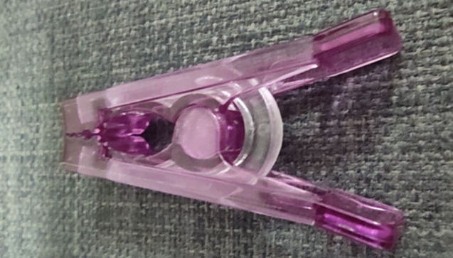
For the on-board LED I made a DIY light guide using a piece of a plastic from the “spring” of a plastic laundry clamp, glued it to the LED and made a "lens" through the encapsulation hole by filling it with glue from a glue gun.

 Michael Gardi
 David Boucher
 bobricius