Parts List:
The links are what I used, but can be of course substituted if found elsewhere
- ThinkPad T60 with working screen and keyboard
- Video Controller Board Kit: M.NT68676.2A HDMI DVI VGA Audio LCD Panel Controller Driver Board
You will need to contact the seller first and give the model of your screen so they can check its compatibility and program the board for it. - 40CM display cable: FIX 30 Pin 30Pin LVDS Cable Fix-30P-D6 2ch 6bit for B154PW01 V.1 40CM Length (cable that comes with kit is too short)
- 12v Power Adapter: Belker 36W Universal Power Adapter
- "K" type power connector for power adapter (I could only find it in this set): SoulBay 34pcs Universal Laptop Notebook Input DC Plug Set Jack Tips for Lenovo Toshiba Dell and Most Laptops
- 1x Male Micro USB connectors: uxcell a15061700ux0139 10PCS 5-Pin Micro USB Type B Male Connector
- 1x HDMI Female Solder Connector: Oiyagai 10pcs Gold Plated HDMI A Type Female Plug Connector with PCB Board Version 1.6 19PIN
- 1x HDMI Male Solder Connector: Uxcell a13110700ux0269 HDMI Male 19 Pins Connector A Type Solder Termination Repair Replace Kit 5 Pcs (Pack of 5)
- Loctite Instant epoxy: Loctite Epoxy Five Minute Instant Mix 0.47-Fluid Ounce Syringe
- HDMI cable
- Parts List and instructions for keyboard conversion: LINK
Misc Parts/Tools List:
- Soldering station
- Solder
- Flux
- Solder Wick
- Wire (I used 26 AWG)
- Microscope or magnifying glass for helping to solder components
- Multimeter
- Xacto Knife or other small cutting tool
- Pliers
T60 Hardware Maintenance Manual: LINK
Converting the display:
After contacting the seller and having them set up the video controller board kit in (2) of the parts list, we need to remove the display from the lid and extend the power cable so that it can comfortably reach the base of the laptop:

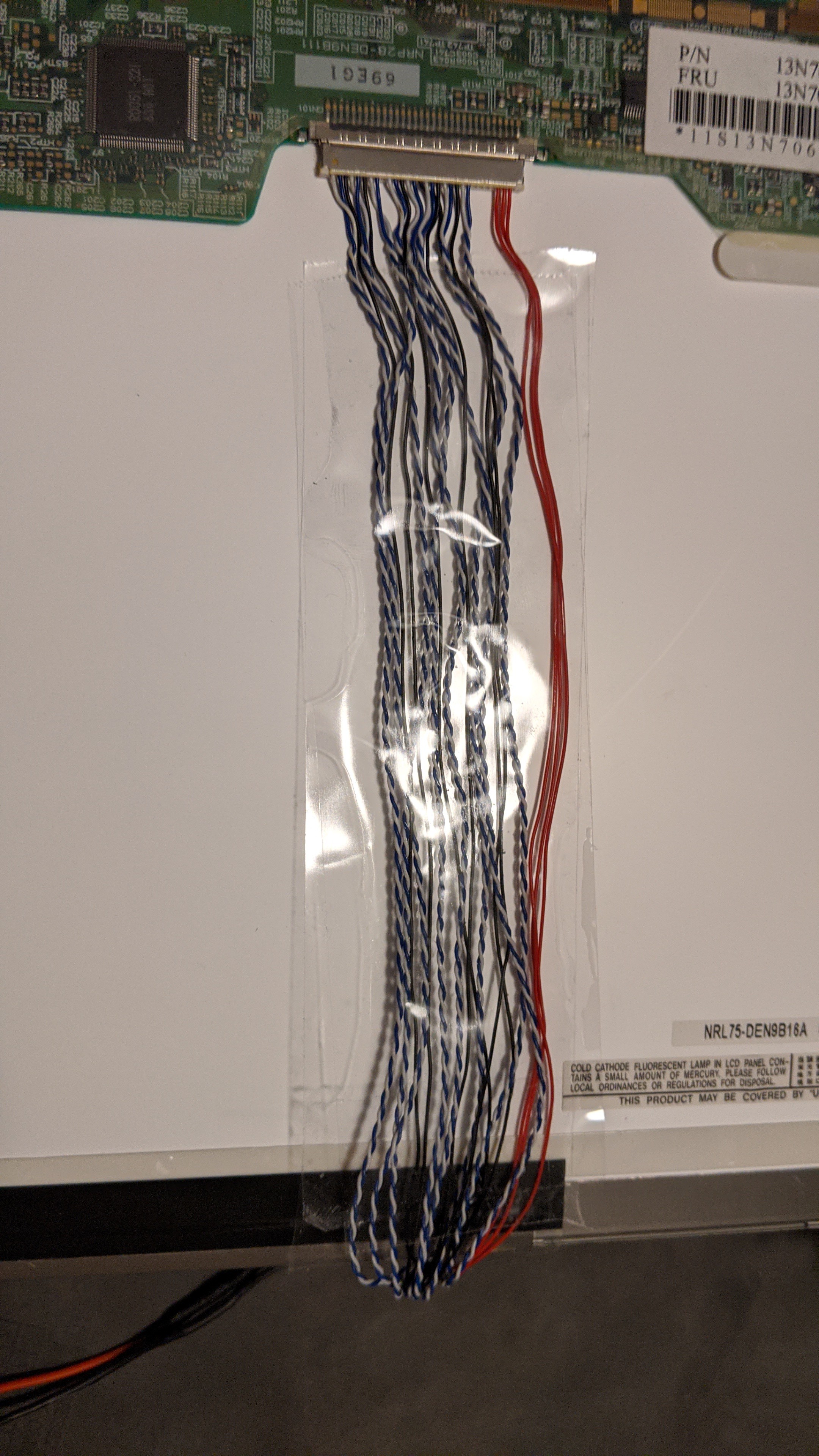
Next, we need to remove the black covering that bundles all the wires of the 40cm cable and spread the wires out flat with tape. Without doing this, the display will not fit back into the lid. We can now swap out the old cable with the 40cm cable:
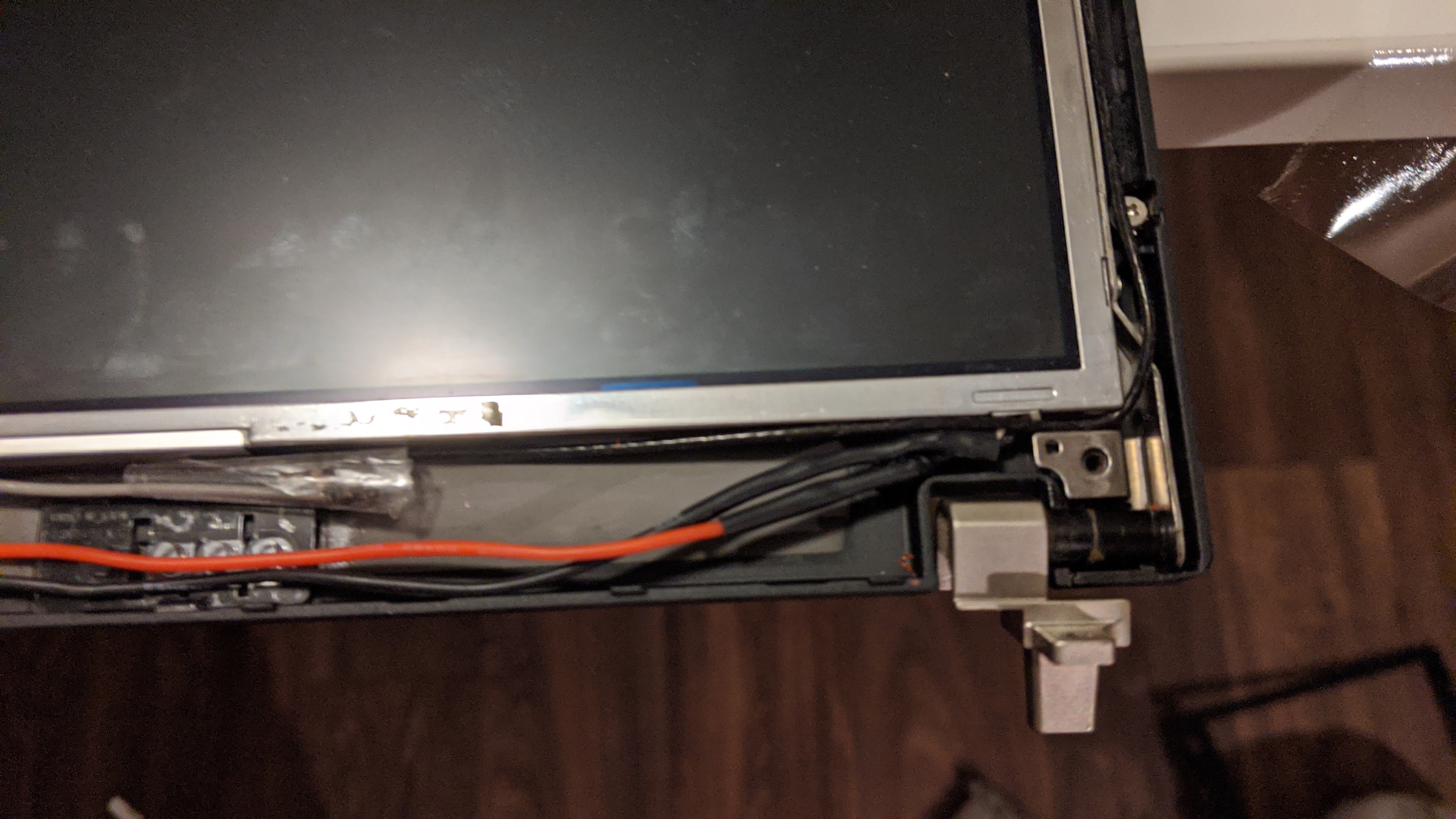
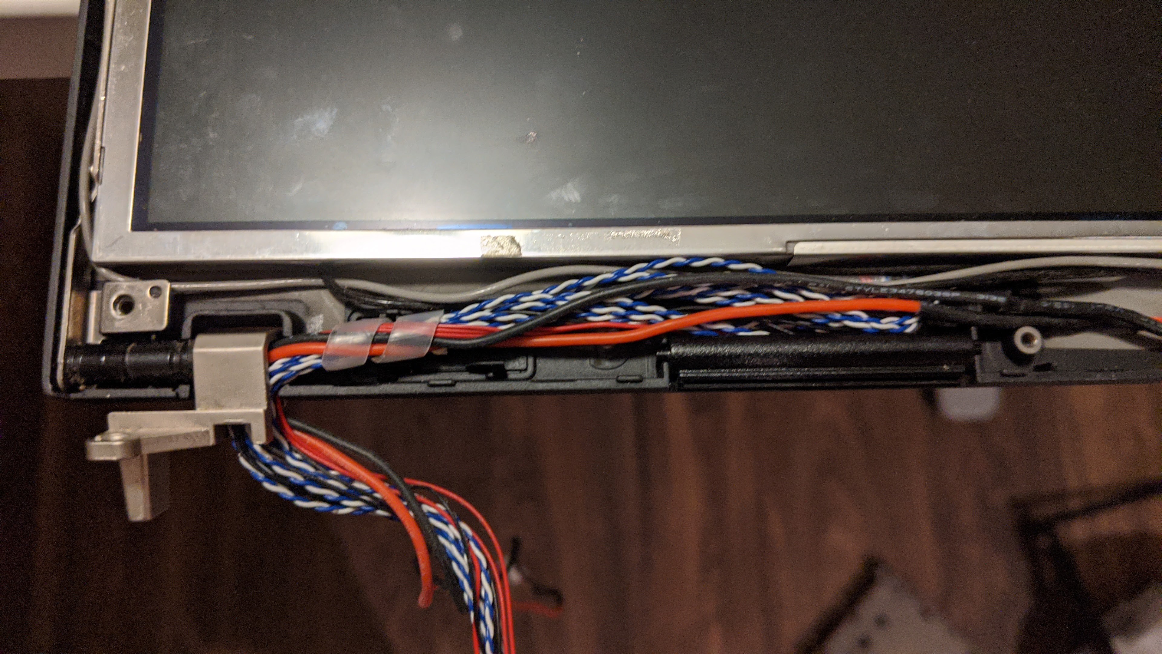
Once that is done, fit the display back into the lid and route the wires to go through the left hinge:
Place the display bezel back on, screw the screws back in, and we are done with the lid portion!
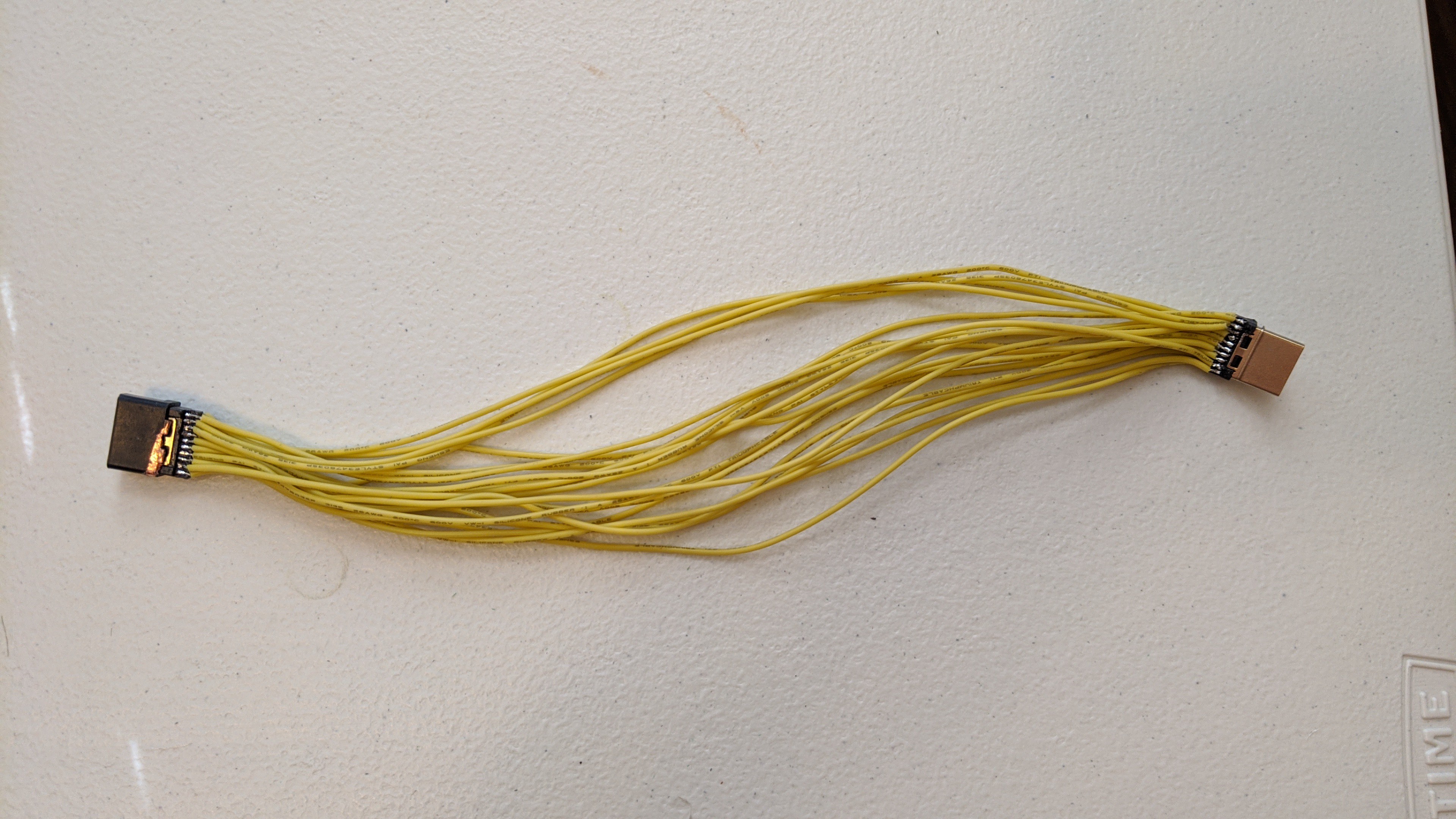
Create the internal HDMI extension cable:
A regular HDMI extension cable is too large to fit inside the case so a new smaller one must be made. Be sure to make the wires as close as possible in length, otherwise the timing could become off and cause image distortion. One side will plug into the video board controller, and the other side will be epoxied to the bottom of the PCMCIA cage of the metal frame. Make sure to test the cable before hand:
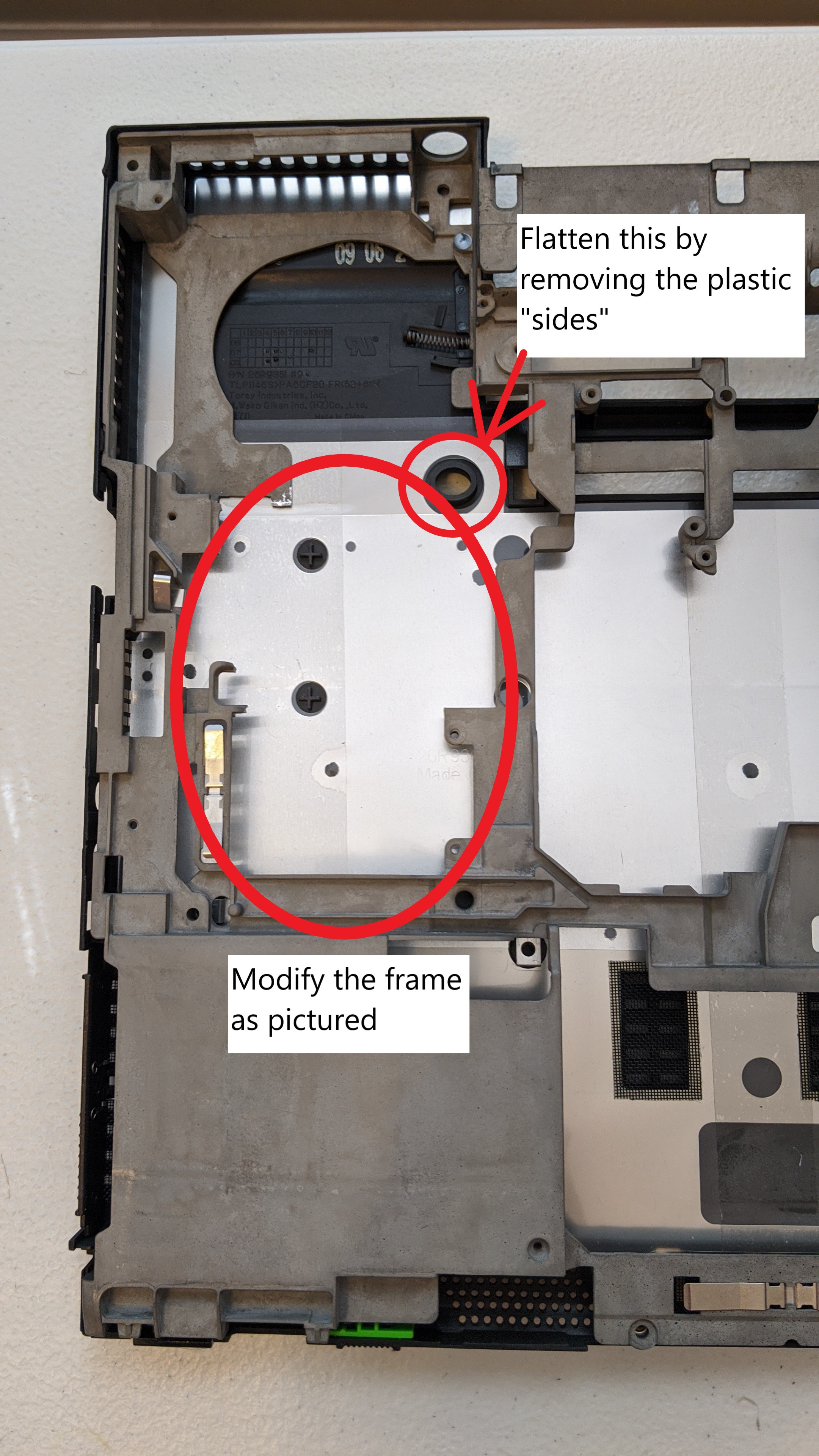
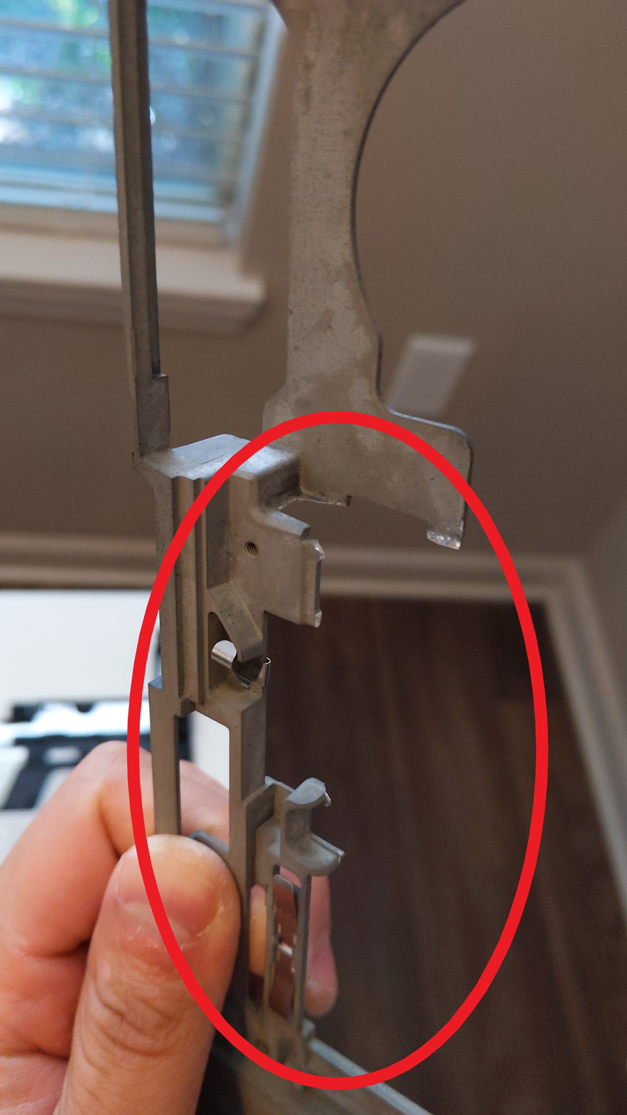
Converting the base:
The base may take a bit of work. Modify the frame and base cover according to the pictures below. I recommend using a dremel if you have one, but you can use some thick pliers like I did. Just be aware of how you are torqueing the pieces that you want to remove, so you don't accidently break off more than intended. Thankfully even after removing these pieces, the frame is still strong.
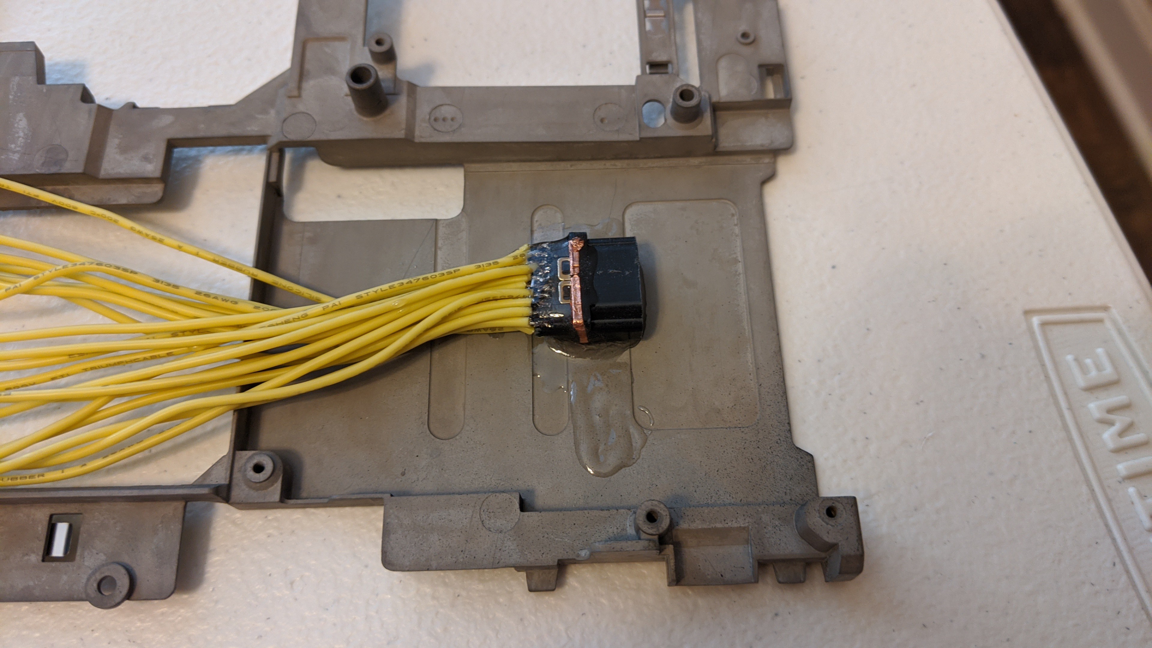
Once done, we can epoxy the HDMI extension cable we made earlier to the bottom of the PCMCIA part of the frame. The female HDMI solder connector has a black plastic covering that I kept when I removed it from an HDMI to Micro HDMI cable. This was to prevent epoxy from seeping into the connector but isn't required if one is more careful. Also if I were to do this again, I would move the connector forward a little so that it isn't as recessed inside the laptop. Just make sure that when aligning the final spot to check that when you push down the spring loaded PCMCIA flap of the base cover, that it does not hit the connector prematurely.
Reusing the I/O ports of the motherboard:
After modifying the base, we need to cut the I/O portion of the motherboard off so we can reuse the ports. I (attempted) to use a Xacto knife. It was not pretty but it managed to get the job done. Next, solder wires onto the USB port and then solder a Male type Micro usb connector on the other end. The micro usb plug will connect to the teensy that drives the keyboard later in the guide.
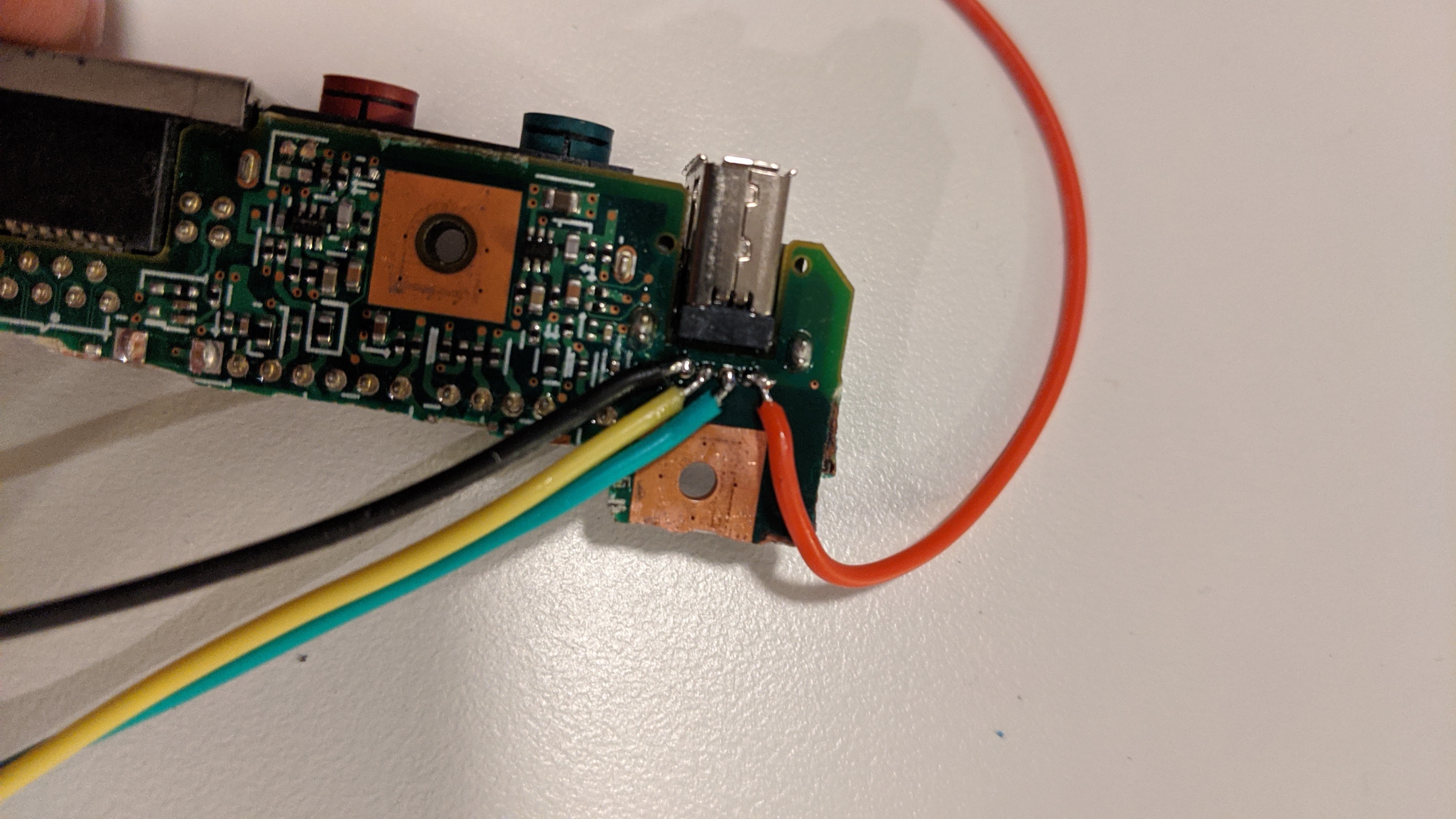
Once that is done, we can setup the video controller board to use the existing power port on the T60:
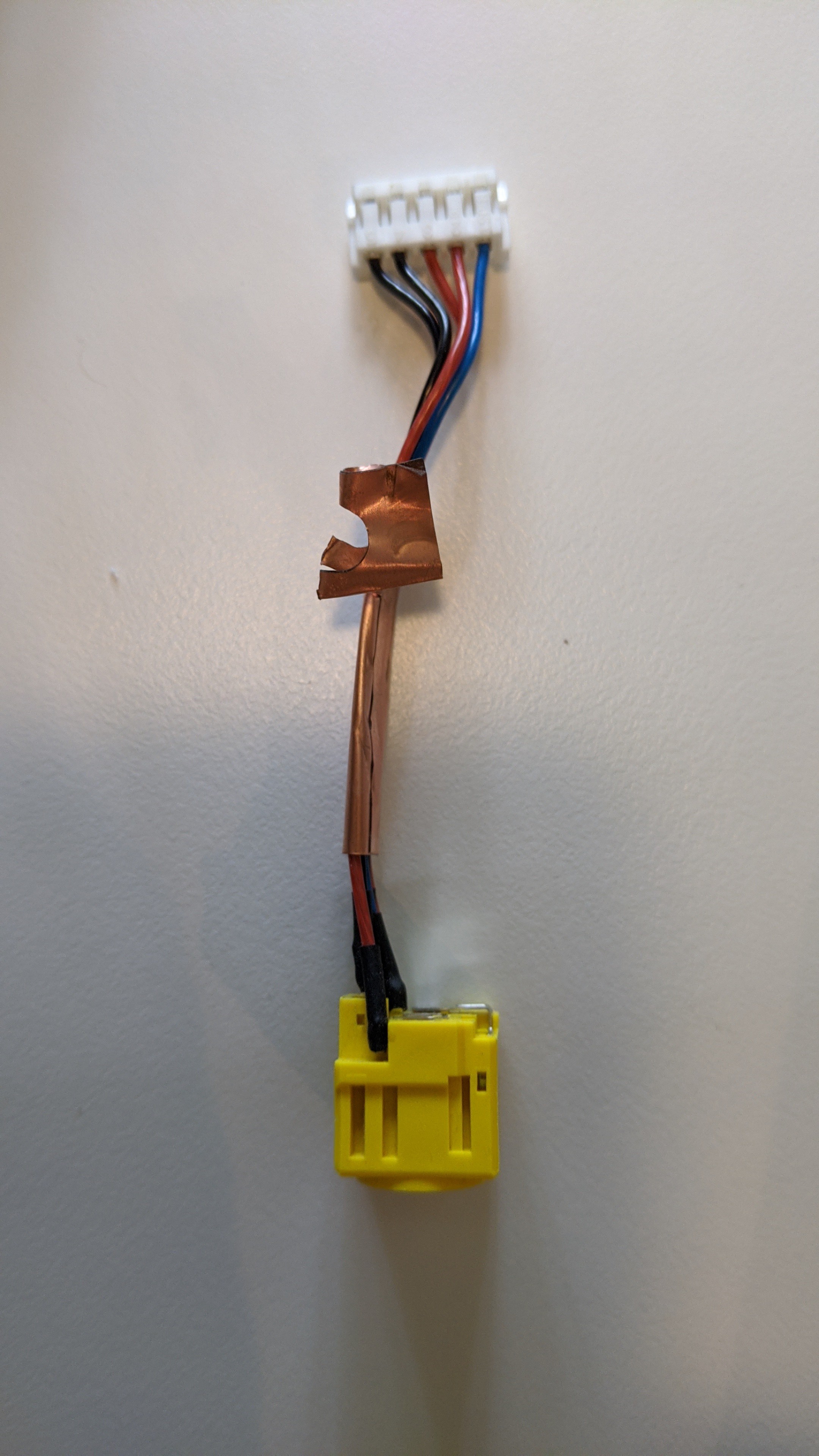
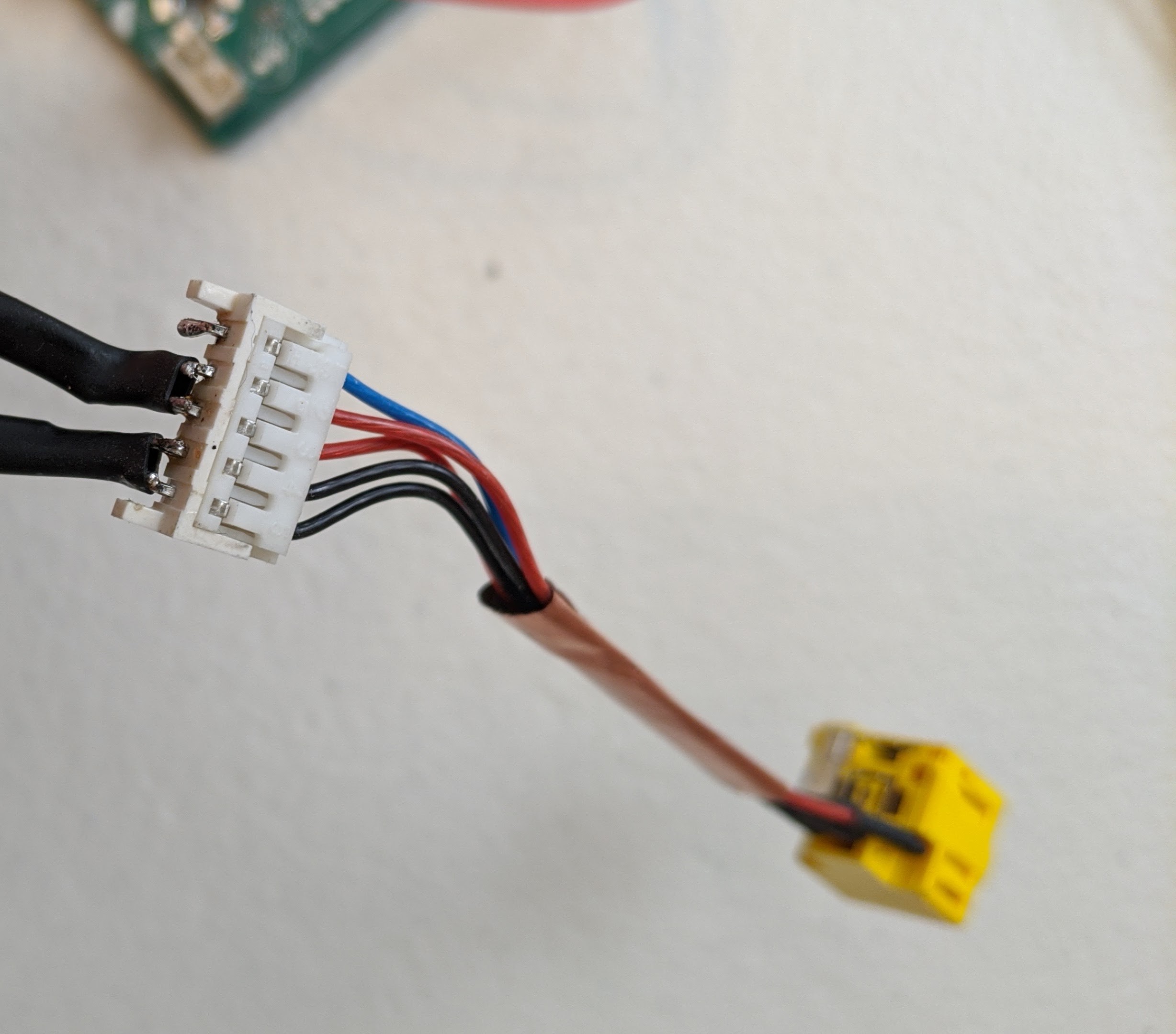
I removed the VGA, DVI, and audio ports and soldered 2 GND and 2 power wires to the bottom of the power port on the video controller board (labeled GND and 12v). I connected it to the power jack of the laptop. I also removed the T60 motherboard power connector and soldered wires to it if I ever needed to remove the yellow DC jack. The "K" type power connector adapter will connect the stock power jack and 12v power supply:

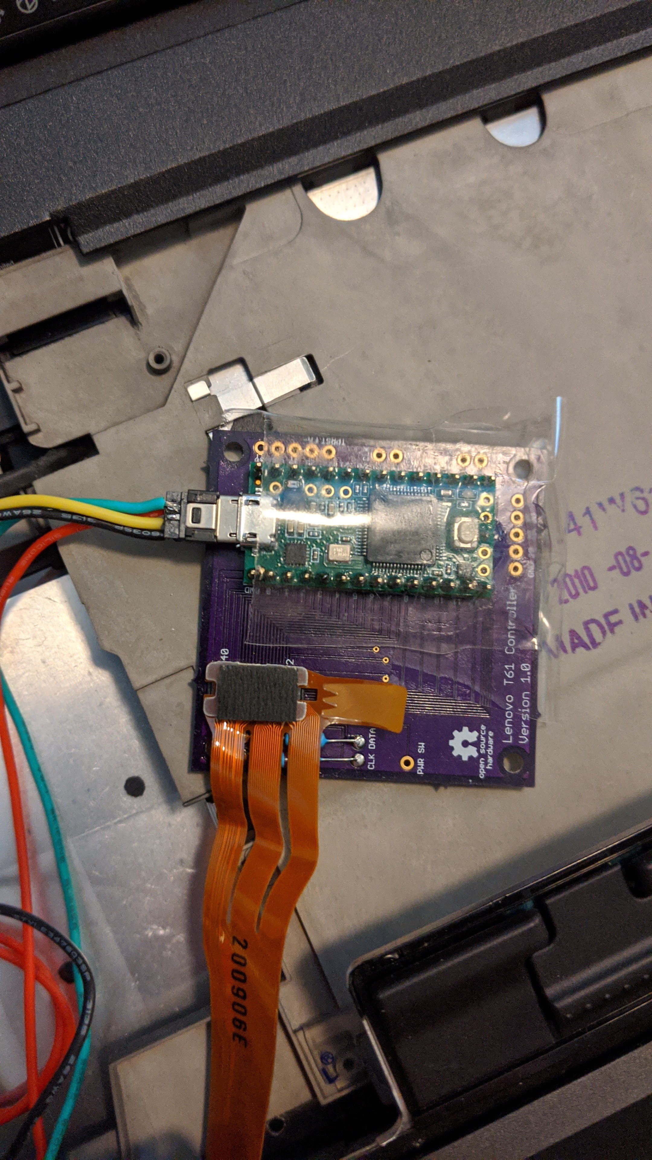
Create the keyboard controller:
See Frank Adam's guide on creating the usb keyboard controller: LINK
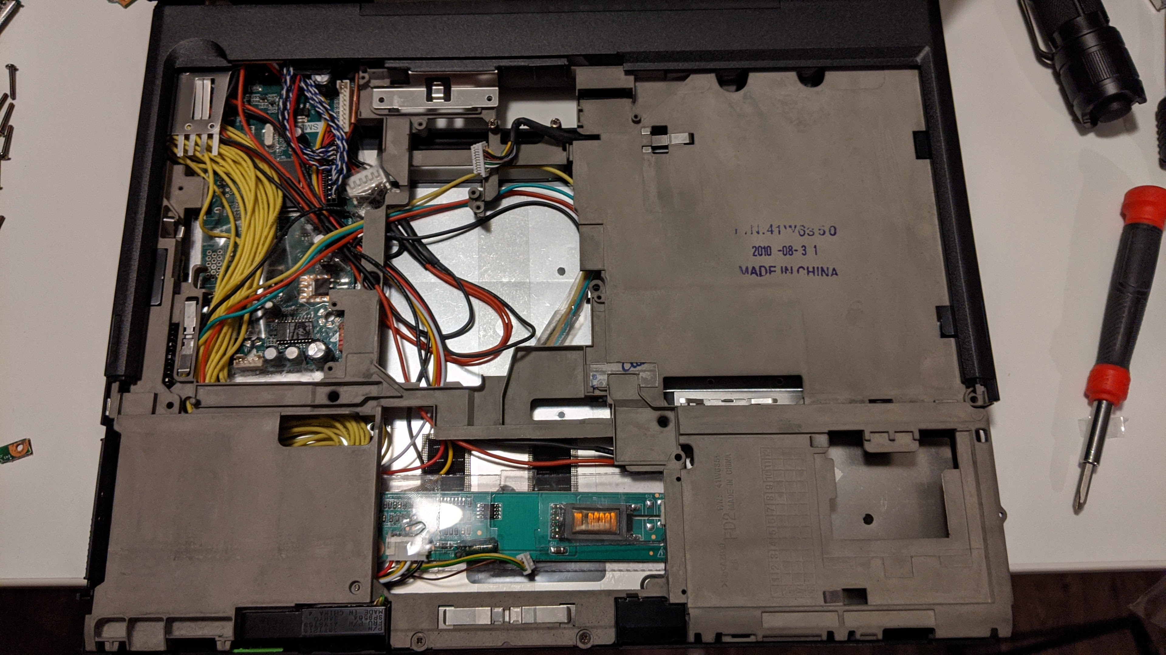
Assembling the base:
Wrap tape around the components to prevent any shorts. Now we can now put everything together. Align the I/O card we made earlier, the video controller board, inverter, keyboard controller board, power jack, and plug in the cables. Also until the video controller board is seated, don't screw the metal frame into the basecover as you will need some space to wiggle the board in. Additionally make sure to screw the yellow DC jack into the frame through the bottom side first. I forgot this and had to unscrew everything again.

Pop back on the keyboard and palmrest and we are good to go! Feel free to ask any questions and I will do my best to answer them. Thank you for reading :)