 tuenhi.n2012
Before getting started, please watch the video below:
Project schematic is as follows:
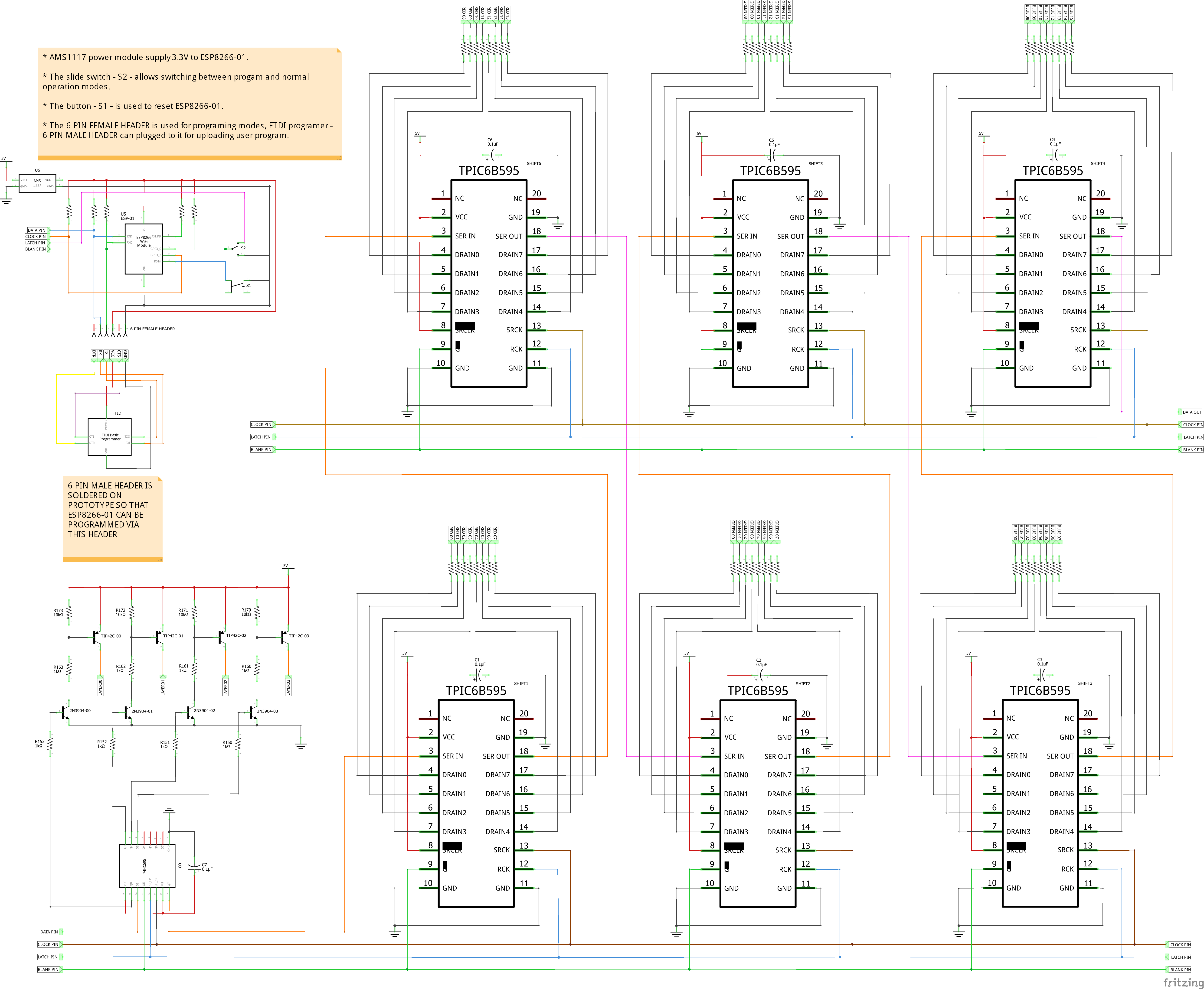
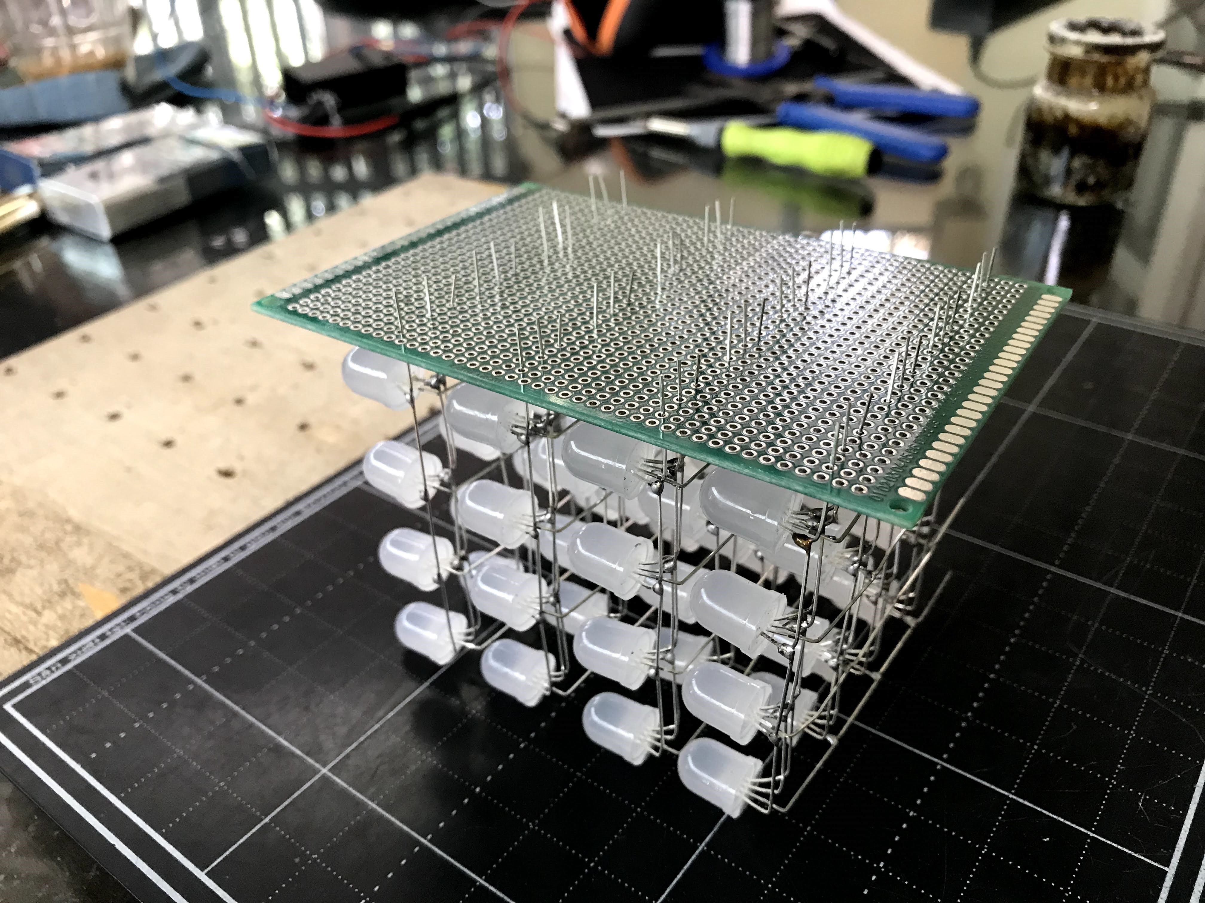
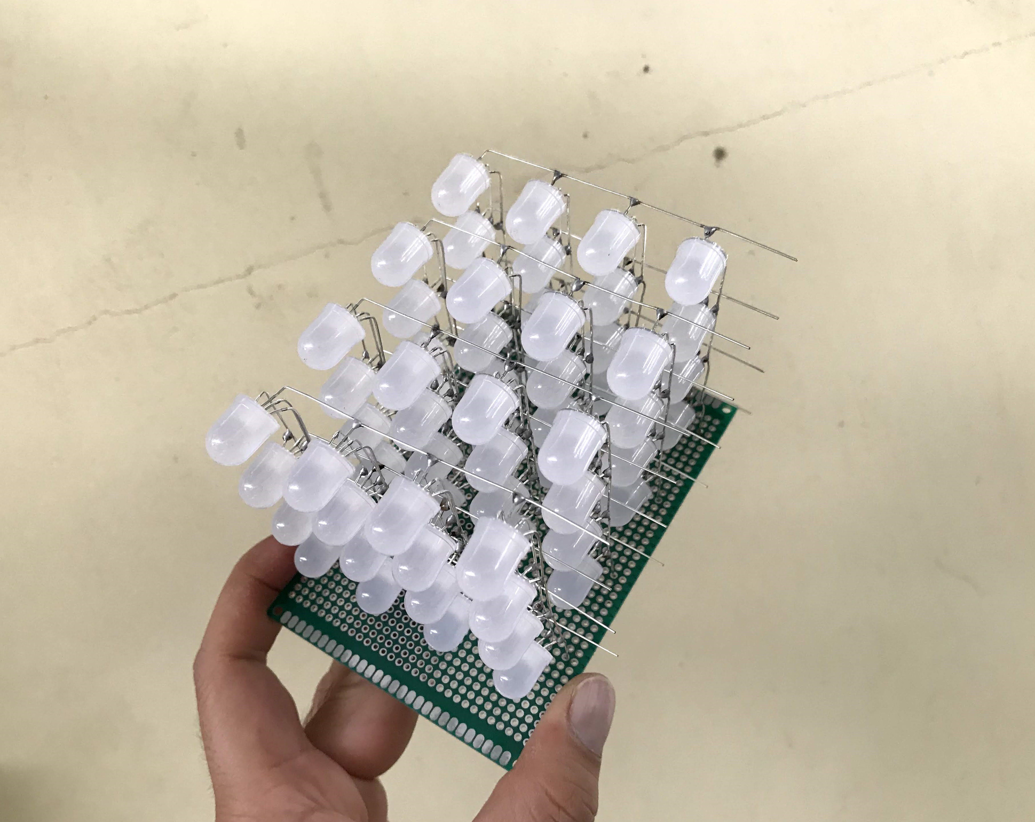
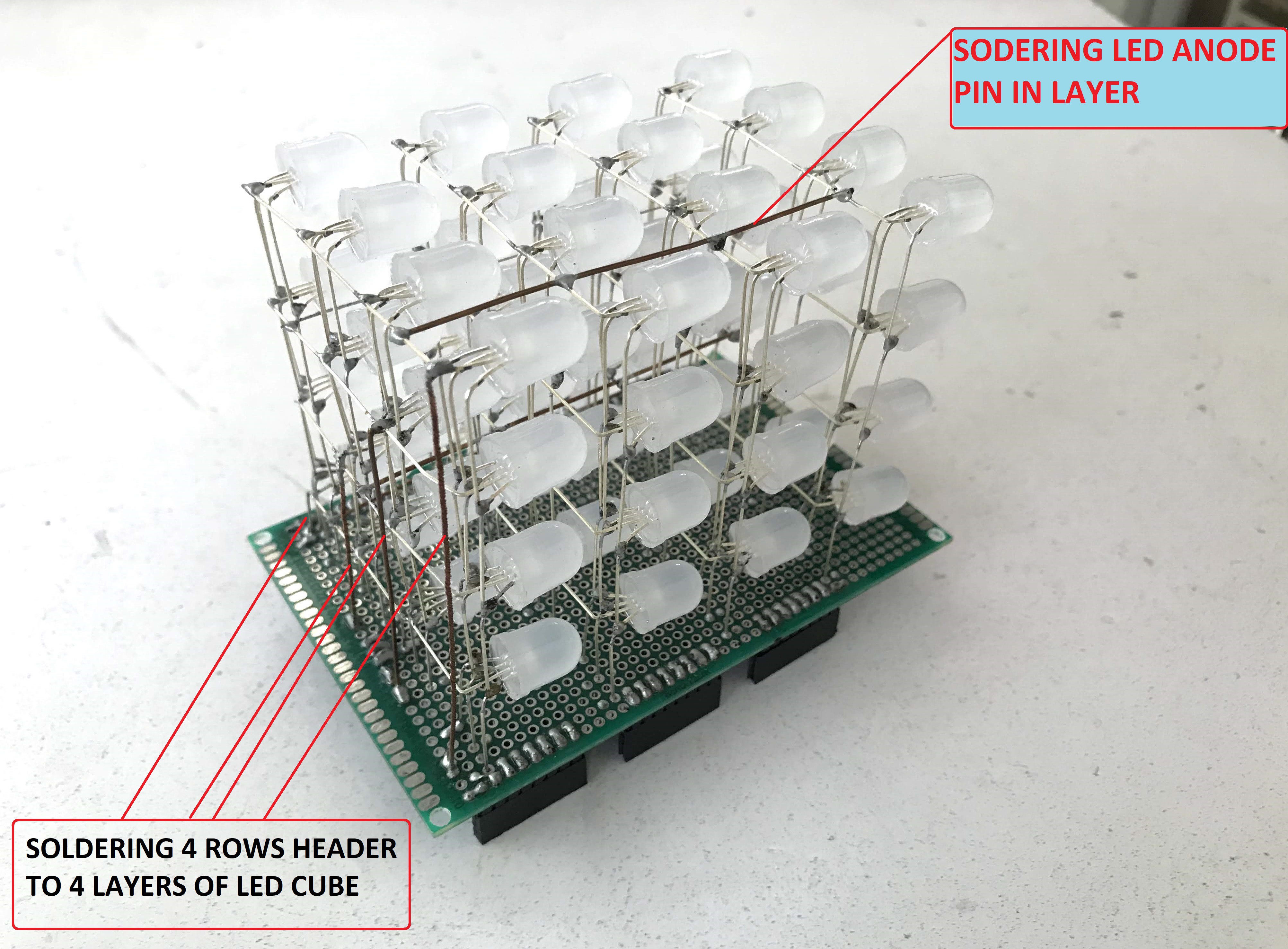
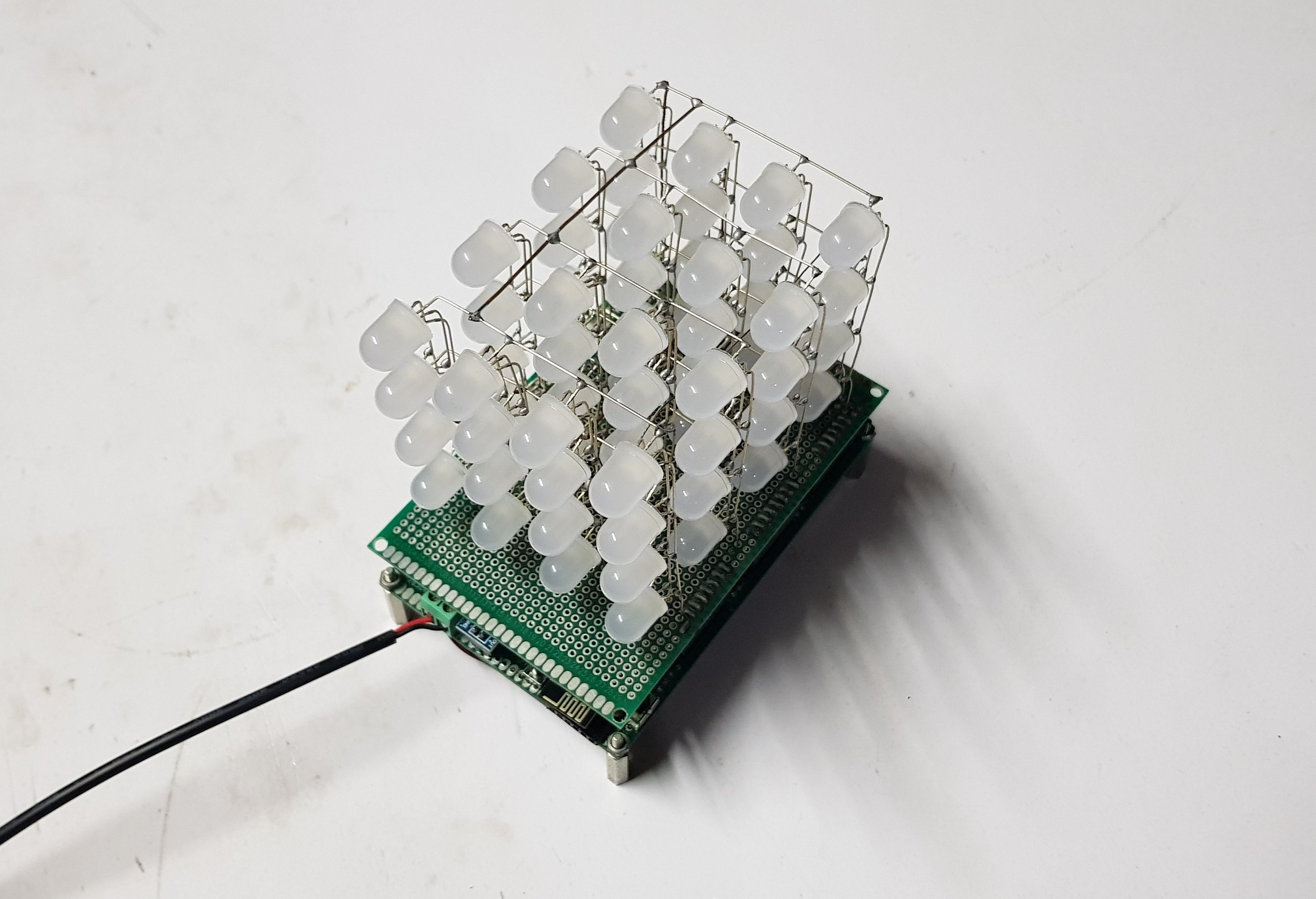
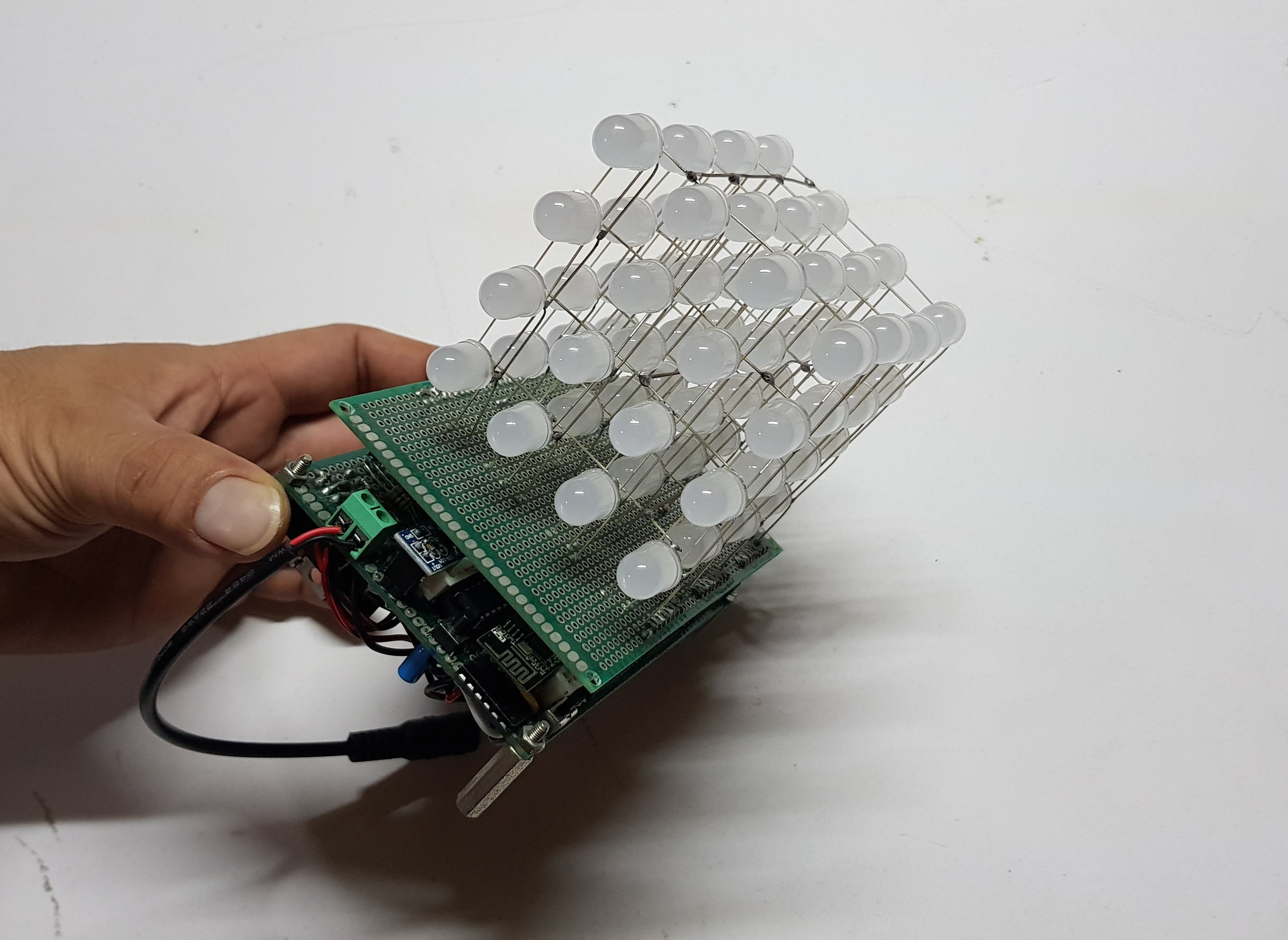
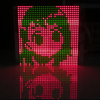
My RGB led cube 4x4x4 includes 64pcs x 10mm RGB LEDs arranged in 04 x LAYERS and each LAYER arranged in 04 x ROWS and 04 x COLUMNS.
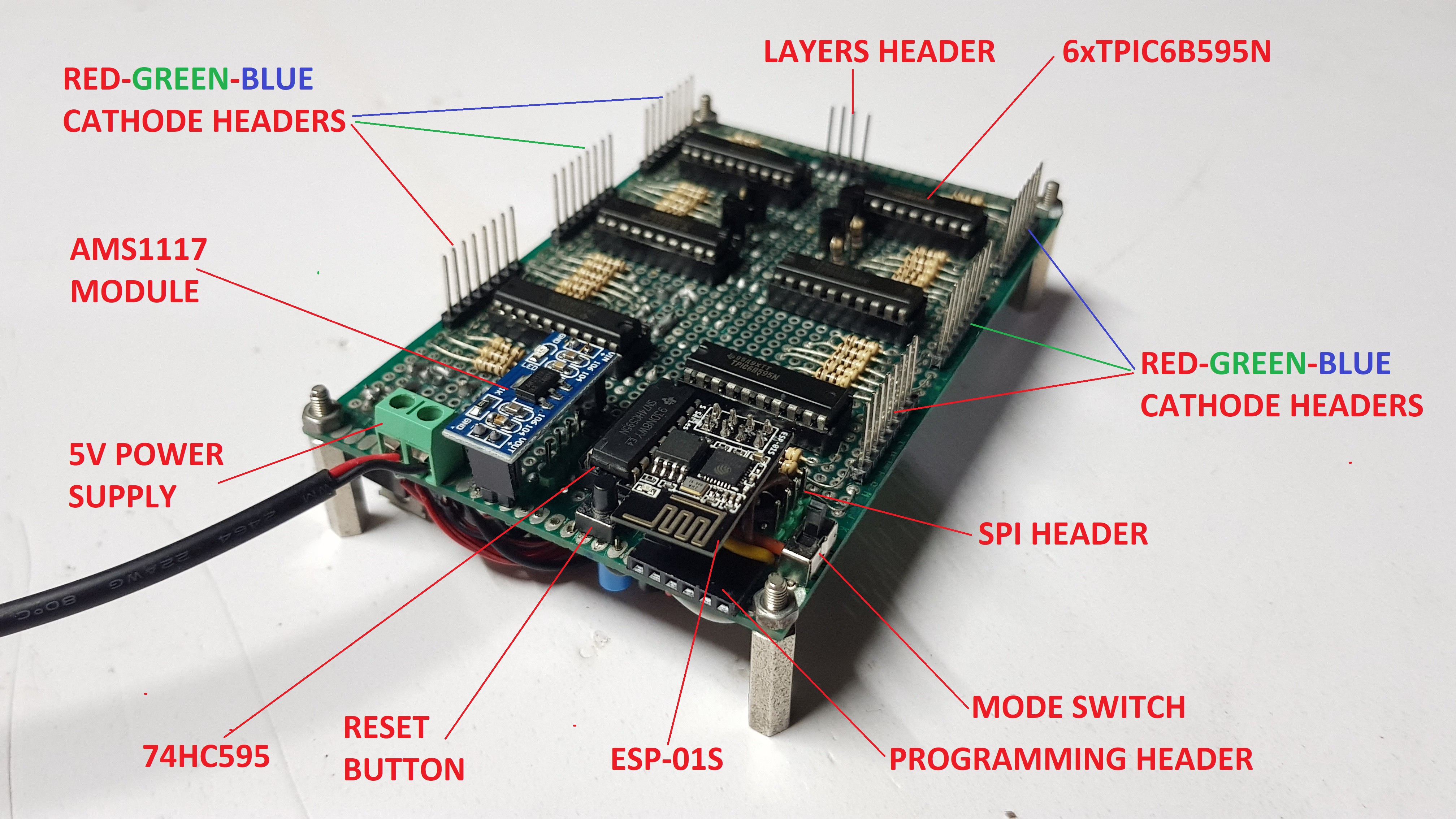
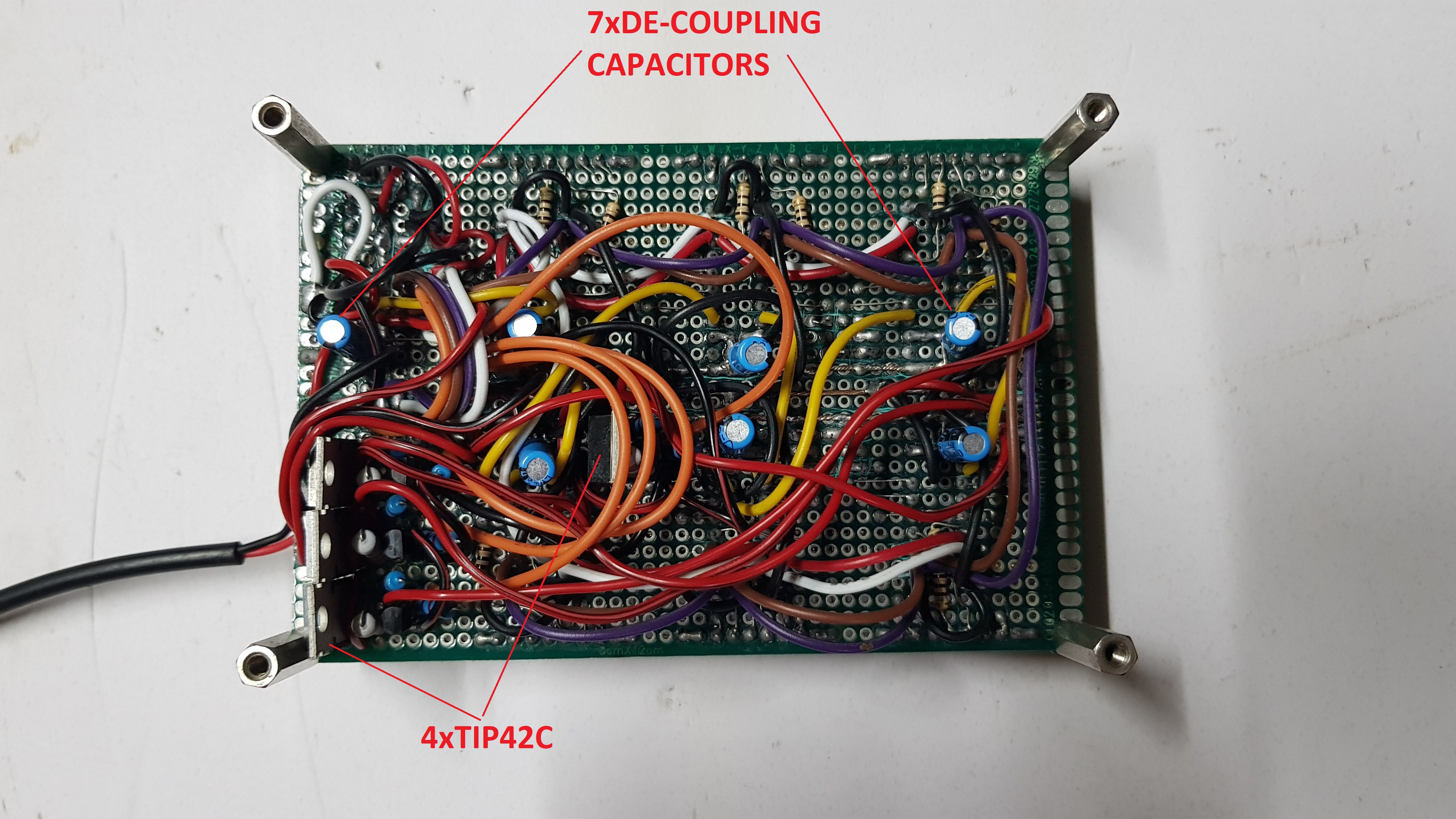
- 04 x LAYERS are controlled by 01pcs x 74HC595 + 04pcs x NPN Transistor 2N3904 + 04pcs x PNP Transistor TIP42C. Outputs of TIP42C are connected to LED ANODES, so the layer needs to be HIGH for an individual LED to turn on. The TIP42C can carry maximum current about 6A.
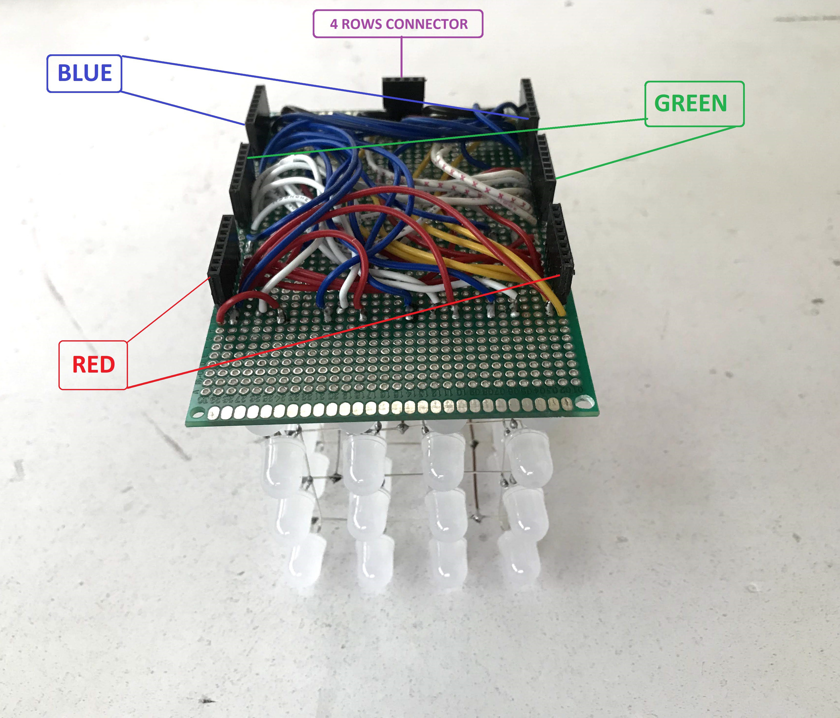
- Each LAYER has 16 x RGB LED arranged in 04 x ROWS and 04 x COLUMNS, which are controlled by 06pcs x TPIC6B595N. Outputs of TPIC6B595N are connected to RED-GREEN-BLUE CATHODES PIN through current limiting resistors R100, so each color pin needs to be LOW to turn on. The TPIC6B595N is high power drains, able to sink 150mA per pin and it cannot source current so they should be connected to LED CATHODES. Each RGB LED has 3 colors and each color of 16pcs x RGB LEDs on a layer is controlled by 2pcs x TPIC6B595N.
- RED COLOR: 02pcs x TPIC6B595N.
- GREEN COLOR: 02pcs x TPIC6B595N.
- BLUE COLOR: 02pcs x TPIC6B595N.
- ESP-01 ESP8266 is including modes slide switch, reset button, programming header, SPI header and AMS1117 power module for converting from 5V to 3.3V.
The schematic below is shown how the ESP-01S can boot up in program mode and normal operation mode:
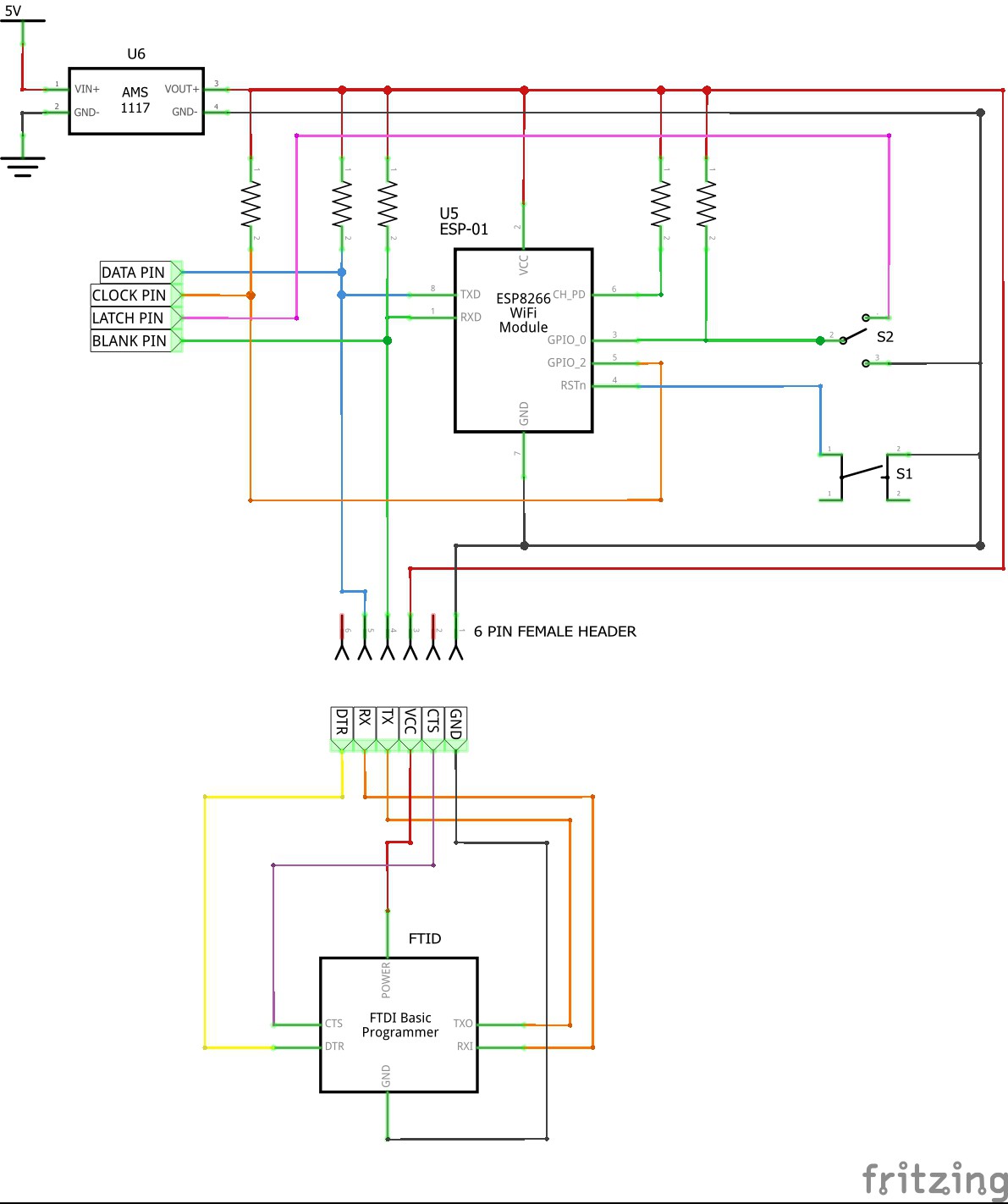
- The button - S1 - is used to reset ESP-01.
- The slide switch - S2 - allows switching between program and normal operation modes.
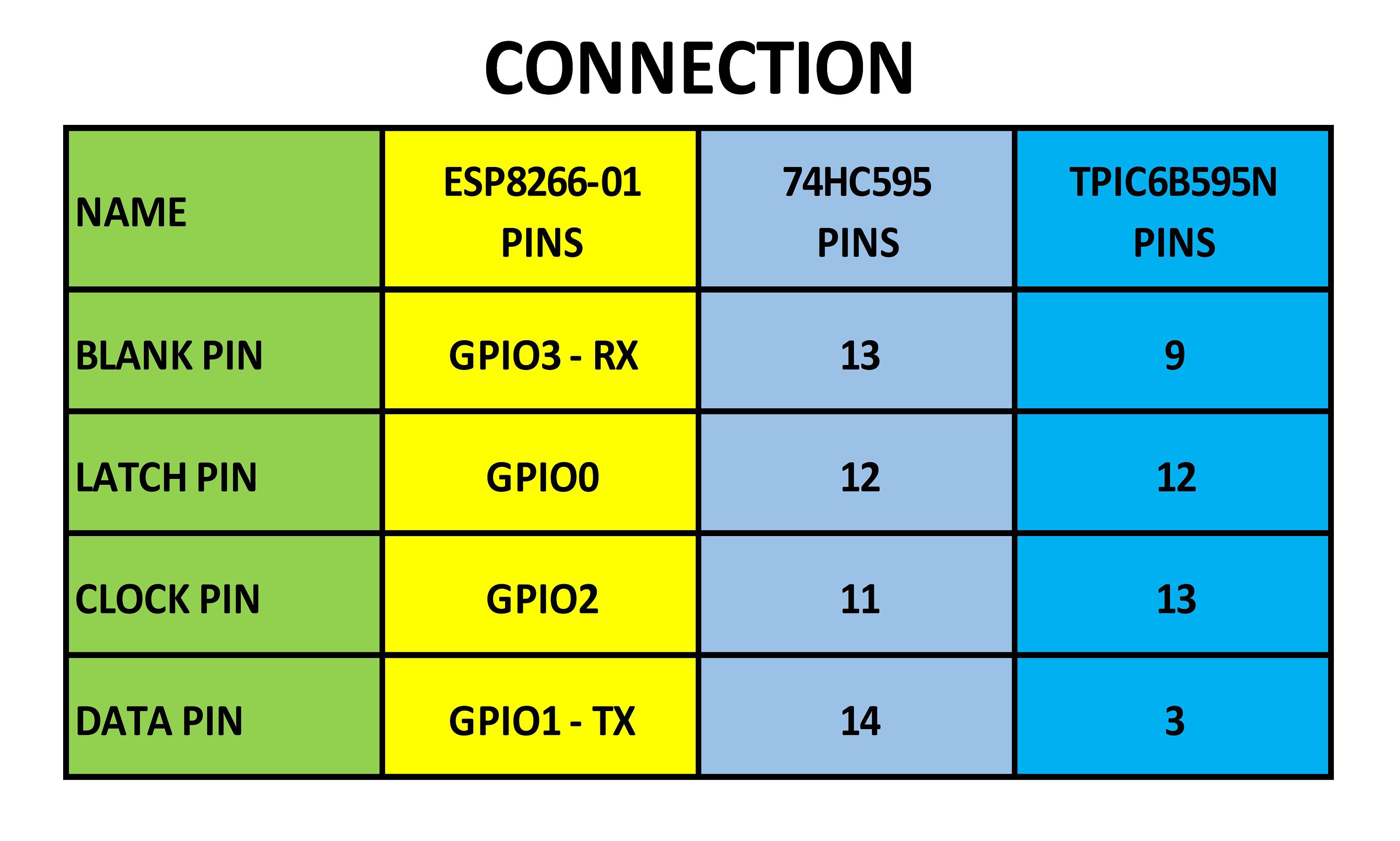
- In normal operation mode, ESP-01S control 4x4x4 RGB led cube by 4 GPIO pins as follows:
- BLANK PIN connecting to GPIO3 - RX
- LATCH PIN connecting to GPIO0
- CLOCK PIN connecting to GPIO2
- DATA PIN connecting to GPIO1 – TX
NOTES:
- AMS1117 power module is used for supplying 3.3V to ESP-01.
- All pull-up resistors are 10Kohm.
- The 6 PIN FEMALE PROGRAMMING HEADER was soldered on control board. In order for uploading the program from Arduino IDE, I can easily plug FTDI programmer into this header, remove SPI header, switch S2 to GND position and ensure the external power is supplied to ESP-01S.


 Hugo
Hugo
 Gerben
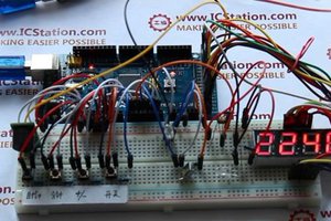
 icstation
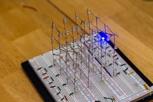
 endevor100
Awesome work! You have a steady hand and great patience =) I have attempted to make a couple LED cubes and they look like they should be named the 3d Eiffel Cube, lol. Getting those LED's perfect like that isnt easy. Thumbs up!