 Vincent
Inspired by Punished Props' and YourGeekFix' videos, I wanted to take a shot at making my own interactive and functional version of the Fallout 76 PipBoy kit from The Wand Company.
This will be my first foray in actually combining my interests and skills into a singular project that also happens to combine my passions: Video games, prop replica's, model building and fiddling around with electronics I know nothing about!
Here's my plan to make that goal a reality. I am not super good at soldering, so I will try to make this project as plug-and-play as possible when it comes to electronics and the like. Just to save myself from spending evenings crying behind my PC ordering new parts that I just burnt up ;).
I will try and update the Project Logs regularly so whoever is reading this little corner of hackaday.io will have their share of progression updates. It's also a good way to show off to friends and family, should they be interested in what project I have taken upon myself!
Here are some videos that inspired me to begin this journey, as I truly am starting off this project from the shoulders of giants.
Punished Props Video:
YourGeekFix Video:
 Here is a pic of the Ikea LIVBOJ I destroyed to put in the Pip Boy Stand:
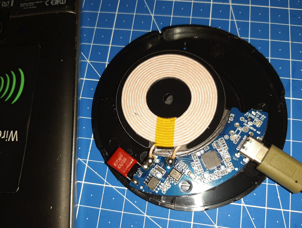
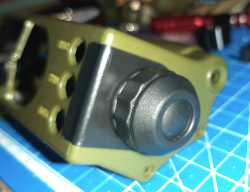
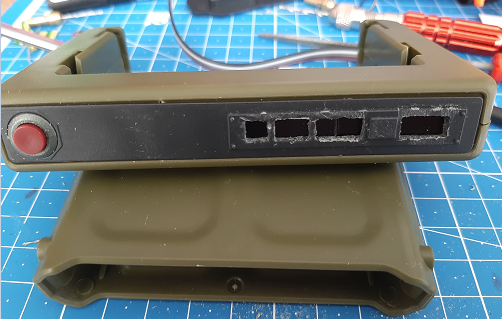
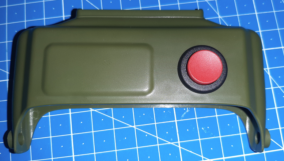
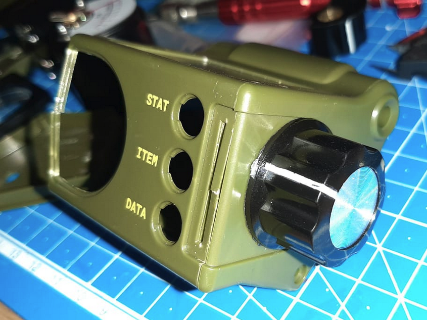 I'm still on the fence whether or not I go for the original or the more industrial-looking knob. Both of them are very easy to install. We'll see when the rest gets done. I got 10 of 'em! And yeah I manhandle my parts. Call it "Natural Weathering" ;).
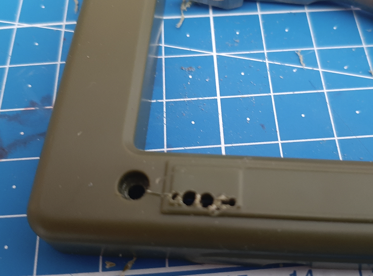 The space on the lower right of the picture is going to be decorated with a black/yellow warning decal, so I thought it would also be aesthetically fitting for wires to come out on both sides. Threading the wire bundle will hopefully also provide a strain relief on the OLED display wire connections, as it's being friction-locked in place.
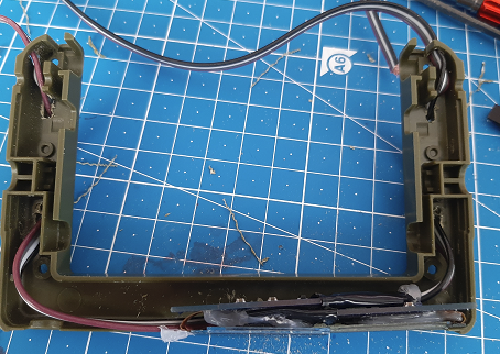
 I will have to hide the crimes a bit, but that's where paint and Milliput come in ;).
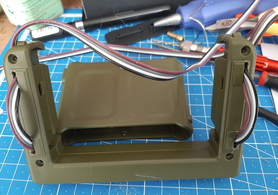 They come out the back, and hopefully do not interfere with the latching mechanism. I couldn't deduce from the manual if those lips on top were required for it to keep hold on something, so I drilled holes to the side of them. You might notice that the colors of the wires are inverted, but that is because one of the OLEDs is upside-down in order to fit against the other OLED screen. They are color coded, so I know which I2C pads I need to solder ;).
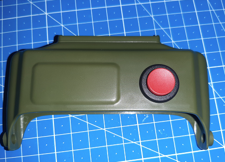
 Looking good, huh? Well, that's it for the Rad Module for now. Hope you enjoy these logs!
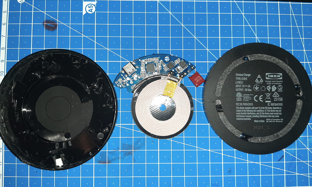
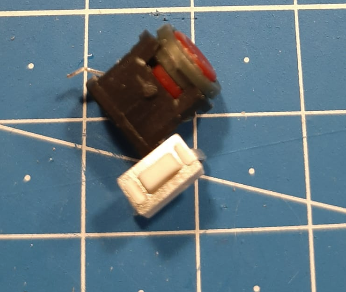
 It's the LP0125CMKW01C - Pushbutton Switch 1CO ON-(ON) Black / Red, by NKK.
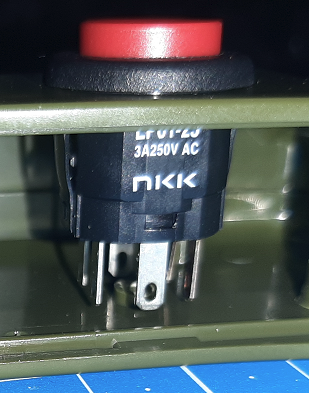
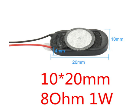 I managed to test out the sounds the "Geiger counter" makes. The speakers are super tiny, and only uses up one GPIO-pin and connects to GND.
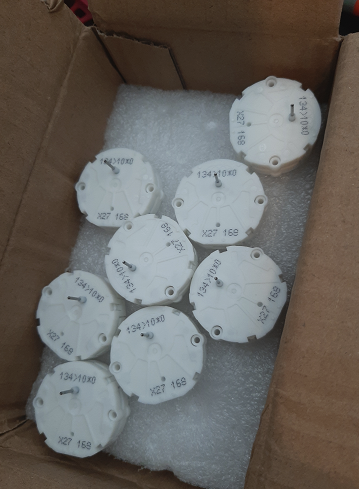
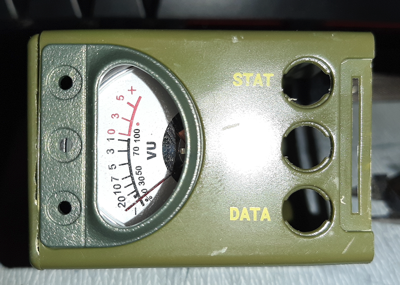
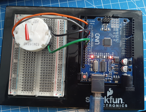 I used part of a Gundam model kit's sprue/runner as a dial gauge. I'll try and whittle it down to a finer point going forward.
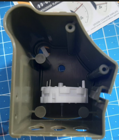
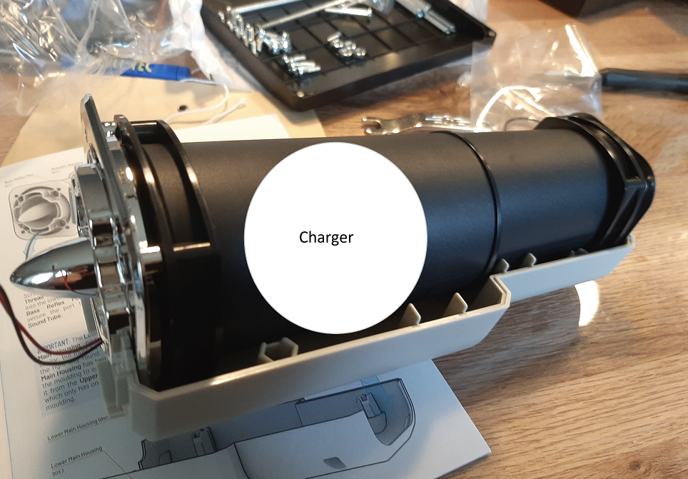
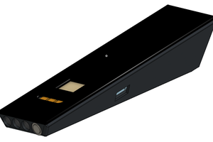
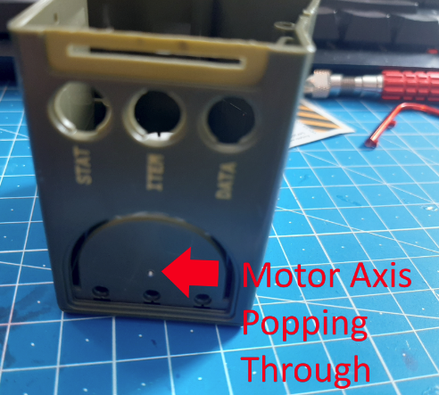 As you can see, I think it will fit pretty well if I remove (part of) the screw struts.
 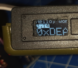 As you can see, there's plenty of room up and downwards of the enclosure to fit in the OLED display.
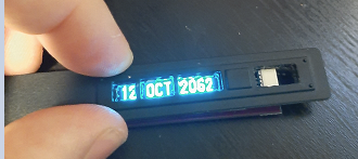
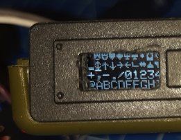 As for pixel real-estate, you can see how many characters I can cram in there. I hope, with some elbow grease I can design a nice rolling counter animation, but I will settle on a digital clock that tells the time correctly!
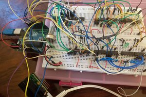
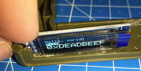 Since I used the Arduino UNO with some DuPont connectors, there's some fitting issues. I think if I directly solder wires to the pins and drill some hole for the wires to go through, it might be a good fit.
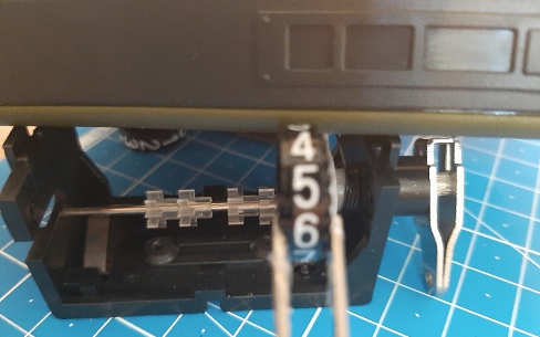 The inset at the top-right of this picture is where the holes would be to show the numbers.
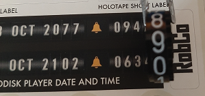


 Matt Bradshaw
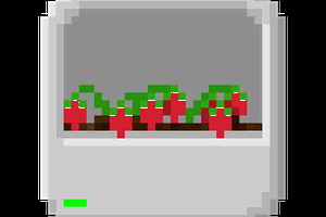
 alpha_ninja
I saw the LILYGO T-Deck may be a potential alternative to the Blackberry Passport in there if you're a programmer.