We are going through the biggest health crisis in recent years due to the increase in the number of cases of Coronavirus (Covid 19).
In some countries, there are not enough tests to detect the presence of the Coronavirus in people, which makes it difficult to correctly count the number of cases and impairs the decision-making of public policies such as the adoption of social isolation to stop the increase in the number of cases or Flexibilization.
One of the main symptoms of Coronavirus is an increase in body temperature above 39ºC, in addition to other symptoms such as pain in the body, difficulty in breathing.
So we need a device that is able to measure body temperature without having to come into direct contact with the person's body to avoid contamination of the device.
For this, we can use the MLX 90614 sensor. It allows the measurement of temperature without having to come into contact with the person's body, as it performs the measurement through infrared radiation.
So, just bring the sensor close to the person's body and perform the temperature measurement.
With the use of this sensor, we were able to identify the first symptoms of the presence of the Coronavirus in a possibly sick person and recommend that she see a doctor.
Based on this, you will develop a NEXTPCB Thermometer using an MLX 90614 infrared sensor with an Arduino Nano. This system will consist of an OLED display to show the temperature value and a button to activate or not the sensor reading.
In addition, we will have a blue led to indicate when the system is on and a red led to indicate when the temperature is above 39 ºC.
Therefore, through this article you will learn:
- Perform the circuit assembly on the protoboard
- Understand how I2C communication works
- Communicate the Arduino Nano with the OLED I2C display
- Communicate the Arduino Nano with the MLX 90614 temperature sensor
- Understand how the MLX 90614 temperature sensor works.
- Develop the NEXTPCB Printed Circuit Board
Now, we will start the full presentation of the development of the Thermometer project with MLX 90614 infrared temperature sensor.
Developing The Thermometer Project With The MLX 90614 Infrared Temperature Sensor
As previously mentioned, the project consists of creating a system to monitor people's temperature using the MLX 90614 infrared temperature sensor.
In figure 1, it is possible to see the circuit mounted on the protoboard to perform the system tests.
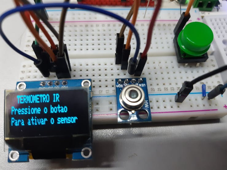
Figure 1 - Screen to start reading the temperature value.
The following message appears in Portuguese on the screen "IR Thermometer - Press the button to activate the sensor".
To activate the temperature reading, you need to press the green button.
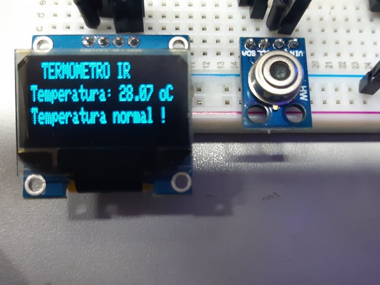
After pressing, the system is activated and the blue LED lights up as shown in figure 2.
1 / 2
In the OLED display in figure 2, the following message appears in Portuguese "IR Thermometer - Temperature: 28.07 and Normal Temperature!".
In addition to displaying the temperature value, this system displays a message indicating whether the temperature is normal or if she needs to see a doctor. This can be seen in figure 3.
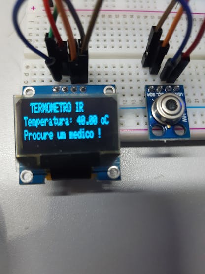
1 / 2 • Figure 3 - System on and temperature above 39º C.
The figure above shows the following message in Portuguese "IR Thermometer - Temperature: 40.00oC and Find a doctor!"
In the figure, the system detected a temperature above 39 ºC and therefore displayed the message: Look for a doctor and switched on the red alert LED.
Now let's go to the list of electronic components needed to assemble the project.
Below, we present the electronic schematic for you to assemble this project on the protoboard.
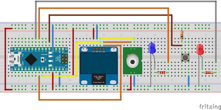
To assemble the device, we need to assemble the circuit on the protoboard as shown in figure 4.
Both the OLED display and the MLX 90614 temperature sensor uses I2C communication to communicate with the Arduino Nano.
I2C Communication
I2C communication - is a communication protocol developed by the company Philips that uses only two wires to carry out the communication between devices (SDA- Serial data line and SCL - Serial clock line).
In our project, two components use this communication: the OLED display and the MLX 90614 sensor.
The Arduino Nano has two specific pins to use this communication, which are the A4 - SDA pins and the A5 SCL pin.
Therefore, we must connect the SDA pins of the OLED display and the sensor to the A4 pin of the Arduino Nano and the SCL pin of both components to the A5 pin of the Arduino Nano.
On the VCC pin of the display and the MLX sensor, we supply 5 V of the Arduino Nano.
And the GND pin of the display and the MLX sensor to the Arduino GND.
To activate the MLX 90614 sensor, we are using a button connected to Arduino digital input 2, this button will be activated at logic level 0.
Thus, we need to place a 10 KΩ pull-up resistor on digital input 2 so that this input does not float when the button is not pressed.
To signal when the sensor is making measurements, we use a blue LED connected to digital output 5 of the Arduino Nano.
To limit the current of the led, a 220 Ω resistor was used.
When the temperature is above 39 ºC, a message will appear on the display and the red LED (connected to digital output 6 of the Arduino Nano) will be accessed to indicate an alert.
To limit the current of the red led, a 220 Ω resistor was used.
After performing the circuit assembly on the protoboard, we need to program our Arduino to read the temperature sensor and display the values on the OLED display.
Next, we will present the complete schedule for this project.
Code to find the device's I2C address
As previously mentioned, we are using two I2C devices. These devices have different addresses and to find these addresses you need to write the firmware below on the Arduino Nano.
The Arduino will read the I2C bus and find the address of the MLX 90614 display and sensor. After that, we will be able to configure the device addresses in our code.
The code is provided below.
#include <Wire.h>
void setup() {
Wire.begin();
Serial.begin(9600);
Serial.println("Scanner I2C");
}

void loop() {
byte erro, endereco;
int dispositivos;

Serial.println("Procurando Dispositivo I2C ...");
dispositivos = 0;

for (endereco = 1; endereco < 127; endereco++ ) {
Wire.beginTransmission(endereco);
erro = Wire.endTransmission();

if (erro == 0) {
Serial.print("Dispositivo I2C encontrado. Endereco 0x");
if (endereco < 16) Serial.print("0");
Serial.print(endereco, HEX);
Serial.println(" !");
dispositivos++;
}

else
if (erro == 4) {
Serial.print("Erro desconhecido no Endereco 0x");
if (endereco < 16) Serial.print("0");
}

}

if (dispositivos == 0)
{
Serial.println("Nenhum dispositivo I2C encontrado\n");
}
else
Serial.println("Scaneamento Concluido\n");
while(Serial);
}
After recording this code on the Arduino Nano, if everything goes well, we will find the following addresses:
I2C device found OLED display. Address 0x3C!
I2C device found MLX 90614 sensor. Address 0x5A! temperature sensor
After finding the addresses of each device, save this information, as we will need it later in our code to read the sensor and communicate with the OLED display.
Next, we will understand the complete step by step to develop the programming logic for this project.
The source code for the project
To build this project we used the logic presented below. Now we will explain the entire structure of this schedule.
Com o comando   temperatura.ambient() realiza a leitura da temperatura do ambiente
temperatura.object() realiza a   leitura da temperatura do objeto
*/
// --- Inclusao de bibliotecas
#include <Wire.h> //INCLUSÃO   DE BIBLIOTECA
#include <Adafruit_GFX.h> //INCLUSÃO   DE BIBLIOTECA
#include <Adafruit_SSD1306.h> //INCLUSÃO   DE BIBLIOTECA
#include <SparkFunMLX90614.h>
Adafruit_SSD1306 display = Adafruit_SSD1306(); //OBJETO   DO TIPO Adafruit_SSD1306
IRTherm temperatura; // Instancia a variavel temperatura   como um objeto do IRTherm
// ----MAPEAMENTO DE HARDWARE
#define B0 2 //   Mapeia o pino 2 como B0
#define led_azul 5 //
#define led_vermelho 6
//--- Declaração de variaveis
float  soma_temp =0,   media_temp =0;
boolean en_sensor =0;
unsigned long   interval = 200;
void setup()
{
Wire.begin(); //INICIALIZA   A BIBLIOTECA WIRE
temperatura.begin(0x5A);
temperatura.setUnit(TEMP_C);
display.begin(0x3C); //INICIALIZA   O DISPLAY COM ENDEREÇO I2C 0x3C
display.setTextColor(WHITE);   //DEFINE A COR DO TEXTO
pinMode(B0,INPUT);
pinMode(led_azul,OUTPUT);
pinMode(led_vermelho,OUTPUT);
Serial.begin(9600);
Serial.println("Termometro   infravermelho ");
Serial.println("Covid   19 ");
}
void loop()
{
if(!digitalRead(B0) && en_sensor==0)
{
en_sensor =1;
display.clearDisplay();
while(digitalRead(B0)==0);
}
if(!digitalRead(B0) && en_sensor==1)
{
en_sensor =0 ;
display.clearDisplay();
digitalWrite(led_azul,0);
while(digitalRead(B0)==0);
}
if(en_sensor   ==1)
{
display.clearDisplay();
digitalWrite(led_azul,1);
if(millis () -   interval >200 )
{
if   (temperatura.read())
{
interval = millis();
for (int i=0;   i<10; i++)
{
soma_temp+= temperatura.object();
delay(10);
}
media_temp = soma_temp /10;
soma_temp =0;
display.clearDisplay();
display.setCursor(10, 0);       // Posiciona o cursor
display.setTextSize(1);       // Define tamanho da fonte
display.print("TERMOMETRO   IR ");
display.setCursor(0, 10);       // Posiciona o cursor
display.setTextSize(1);        // Define tamanho da fonte
display.print("Temperatura: " + String(media_temp,   2));
display.println("   oC ");
Serial.print("Temperatura   objeto :");
Serial.print(media_temp,   2);
Serial.println("   oC ");
if(media_temp   >39 )
{
display.setCursor(0, 20);       // Posiciona o cursor
display.setTextSize(1);        // Define tamanho da fonte
display.print("Procure   um medico !" );
digitalWrite(led_vermelho,1);
}
else
{
display.setCursor(0, 20);       // Posiciona o cursor
display.setTextSize(1);        // Define tamanho da fonte
display.print("Temperatura   normal !" );
digitalWrite(led_vermelho,0);
}
display.display();
}
}
}
else
{
display.clearDisplay();
display.setCursor(10, 0);       // Posiciona o cursor
display.setTextSize(1);       // Define tamanho da fonte
display.print("TERMOMETRO   IR ");
display.setCursor(0, 10);       // Posiciona o cursor
display.setTextSize(1);       // Define tamanho da fonte
display.print("Pressione   o botao");
display.setCursor(0, 20);
display.print("Para   ativar o sensor");
display.display();
}
}
To carry out this project we will use 4 libraries.
- Wire - This library is not necessary to install, as it is already the default of the Arduino IDE, this library configures the peripherals to perform I2C communication.
- Adafruit GFX and Adafruit SSD1306 - Both libraries are required to communicate with the OLED display.
- SparkFunMLX90614 - To communicate with the MLX 90614 sensor.
All project libraries and source code can be downloaded through this link - Library download
Now, we will present the programming logic developed in a few steps.
1st step -Inclusion of all necessary libraries for code development
#include <Wire.h> //INCLUSÃO DE BIBLIOTECA
#include <Adafruit_GFX.h> //INCLUSÃO DE BIBLIOTECA
#include <Adafruit_SSD1306.h> //INCLUSÃO DE BIBLIOTECA
#include <SparkFunMLX90614.h>
2nd step - We define two objects: Display and sensor using the commands below.
Adafruit_SSD1306 display = Adafruit_SSD1306(); //OBJETO DO TIPO Adafruit_SSD1306
IRTherm temperatura; // Instancia a variavel temperatura como um objeto do IRTherm
3rd step - Hardware mapping
// ----MAPEAMENTO DE HARDWARE
#define B0 2 // Mapeia o pino 2 como B0
#define led_azul 5 //
#define led_vermelho 6
The hardware mapping helps us to name the outputs or inputs of the microcontroller with the name of the physical component that they will trigger which helps when developing the code.
#define - Command to name a pin, const int could be used, but define takes up less memory space than const int.
4th step - Declaration of variables
//--- Declaração de variaveis
float soma_temp =0, media_temp =0;
boolean en_sensor =0;
unsigned long interval = 200;
Next, we will start our setup function, which is the function where we perform the input and output configurations and configuration of the I2C peripherals, serial communication speed to display the values on the serial monitor.
5th step - Start of the void setup () function
void setup()
{

Wire.begin(); //INICIALIZA A BIBLIOTECA WIRE
temperatura.begin(0x5A);
temperatura.setUnit(TEMP_C);

display.begin(0x3C); //INICIALIZA O DISPLAY COM ENDEREÇO I2C 0x3C
display.setTextColor(WHITE); //DEFINE A COR DO TEXTO

pinMode(B0,INPUT);
pinMode(led_azul,OUTPUT);
pinMode(led_vermelho,OUTPUT);

Serial.begin(9600);
Serial.println("Termometro infravermelho ");
Serial.println("Covid 19 ");
}
In the function Temperatura.begin () - we must put the address found with the code I2C scanner. Our address is 0x5A.
Already the command temperatura.setUnit(TEMP_C); determines the measurement unit.
Finally, we config the address of the display and text color of the display as is shown below.
display.begin(0x3C); //INICIALIZA O DISPLAY COM ENDEREÇO I2C 0x3C
display.setTextColor(WHITE); //DEFINE A COR DO TEXTO
7th Step - The void loop () function
This function will execute your programming logic. The full source code is presented below.
void loop()
{
if(!digitalRead(B0) && en_sensor==0)
{
en_sensor =1;
display.clearDisplay();
while(digitalRead(B0)==0);
}
if(!digitalRead(B0) && en_sensor==1)
{
en_sensor =0 ;
display.clearDisplay();
digitalWrite(led_azul,0);
while(digitalRead(B0)==0);
}
if(en_sensor ==1)
{
display.clearDisplay();
digitalWrite(led_azul,1);
if(millis () - interval >200 )
{
if (temperatura.read())
{
interval = millis();
for (int i=0; i<10; i++)
{
soma_temp+= temperatura.object();
delay(10);
}
media_temp = soma_temp /10;
soma_temp =0;
display.clearDisplay();
display.setCursor(10, 0); // Posiciona o cursor
display.setTextSize(1); // Define tamanho da fonte
display.print("TERMOMETRO IR ");
display.setCursor(0, 10); // Posiciona o cursor
display.setTextSize(1); // Define tamanho da fonte
display.print("Temperatura: " + String(media_temp, 2));
display.println(" oC ");
Serial.print("Temperatura objeto :");
Serial.print(media_temp, 2);
Serial.println(" oC ");
if(media_temp >39 )
{
display.setCursor(0, 20); // Posiciona o cursor
display.setTextSize(1); // Define tamanho da fonte
display.print("Procure um medico !" );
digitalWrite(led_vermelho,1);
}
else
{
display.setCursor(0, 20); // Posiciona o cursor
display.setTextSize(1); // Define tamanho da fonte
display.print("Temperatura normal !" );
digitalWrite(led_vermelho,0);
}
display.display();
}
}
}
else
{
display.clearDisplay();
display.setCursor(10, 0); // Posiciona o cursor
display.setTextSize(1); // Define tamanho da fonte
display.print("TERMOMETRO IR ");
display.setCursor(0, 10); // Posiciona o cursor
display.setTextSize(1); // Define tamanho da fonte
display.print("Pressione o botao");
display.setCursor(0, 20);
display.print("Para ativar o sensor");
display.display();
}
}
First, we check if the button was pressed or not, if it is not pressed we display the following message:
display.clearDisplay();
display.setCursor(10, 0); // Posiciona o cursor
display.setTextSize(1); // Define tamanho da fonte
display.print("TERMOMETRO IR ");
display.setCursor(0, 10); // Posiciona o cursor
display.setTextSize(1); // Define tamanho da fonte
display.print("Pressione o botao");
display.setCursor(0, 20);
display.print("Para ativar o sensor");
display.display();
display.clearDisplay(); - função para limpar o display
Whenever we write something on the display we must use the command display.display (); to update the display.
Pressing the button activates the flag en_sensor with the value 1. Thus, if en_sensor is equal at 1, the program will enter the condition below.
if(en_sensor ==1)
{
display.clearDisplay();
digitalWrite(led_azul,1);
if(millis () - interval >200 )
{
if (temperatura.read())
{
interval = millis();
for (int i=0; i<10; i++)
{
soma_temp+= temperatura.object();
delay(10);
}
media_temp = soma_temp /10;
soma_temp =0;
display.clearDisplay();
display.setCursor(10, 0); // Posiciona o cursor
display.setTextSize(1); // Define tamanho da fonte
display.print("TERMOMETRO IR ");
display.setCursor(0, 10); // Posiciona o cursor
display.setTextSize(1); // Define tamanho da fonte
display.print("Temperatura: " + String(media_temp, 2));
display.println(" oC ");
Serial.print("Temperatura objeto :");
Serial.print(media_temp, 2);
Serial.println(" oC ");
if(media_temp >39 )
{
display.setCursor(0, 20); // Posiciona o cursor
display.setTextSize(1); // Define tamanho da fonte
display.print("Procure um medico !" );
digitalWrite(led_vermelho,1);
}
else
{
display.setCursor(0, 20); // Posiciona o cursor
display.setTextSize(1); // Define tamanho da fonte
display.print("Temperatura normal !" );
digitalWrite(led_vermelho,0);
}
display.display();
}
Under this condition, we turn on the blue led and check if 200 ms has passed. If so, we check if it is being read using the function below.
temperatura.read())
After the reading starts, we take 10 readings and average the values to be displayed on the screen, as shown in the code below.
media_temp = soma_temp /10;
soma_temp =0;
display.clearDisplay();
display.setCursor(10, 0); // Posiciona o cursor
display.setTextSize(1); // Define tamanho da fonte
display.print("TERMOMETRO IR ");
display.setCursor(0, 10); // Posiciona o cursor
display.setTextSize(1); // Define tamanho da fonte
display.print("Temperatura: " + String(media_temp, 2));
display.println(" oC ");
Serial.print("Temperatura objeto :");
Serial.print(media_temp, 2);
Serial.println(" oC ");
The temperature.object () command reads the temperature of the object. The temperature.ambient command reads the ambient temperature.
After taking the temperature measurement, we check if the value is greater than 39ºC. If it is true, we will activate the red LED. The code is presented below.
if(media_temp >39 )
{
display.setCursor(0, 20); // Posiciona o cursor
display.setTextSize(1); // Define tamanho da fonte
display.print("Procure um medico !" );
digitalWrite(led_vermelho,1);
}

else

{
display.setCursor(0, 20); // Posiciona o cursor
display.setTextSize(1); // Define tamanho da fonte
display.print("Temperatura normal !" );
digitalWrite(led_vermelho,0);
}

display.display();
In addition, we have developed an electronic board with NEXTPCB Printed Circuit Board. This board will allow you to assemble this prototype and use it in your projects.
NEXTPCB Printed Circuit Board Project
In the figure below we present the project's prototype in its 3D version.
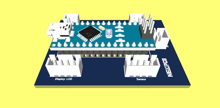
This project was developed from the following electronic schematic.
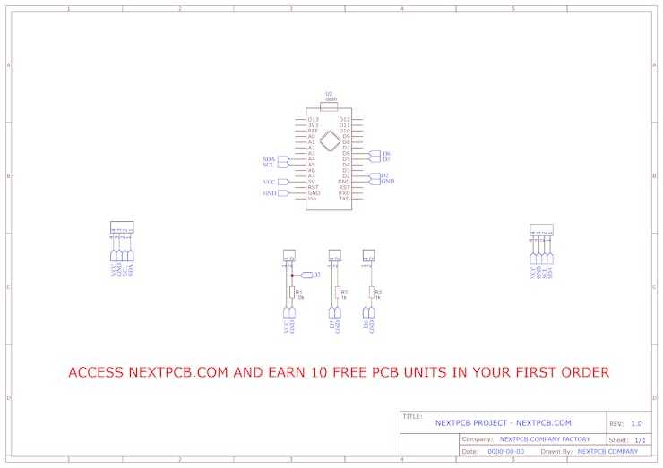
Finally, we finish this project and you can download the Gerber files and obtain your 10 PCBs in NEXTPCB.COM. The link to download is: Gerber files download
Conclusion
In this article, we learned how to build a thermometer with the MLX 90614 sensor with the Arduino. For this, we use an OLED display to display the measurements and create a useful device to measure the temperature of people and environments.
In this way, we can contribute to the fight against the pandemic that we are currently experiencing.
A suggestion for future projects is to add a memory card module to save the measurements and create a datalogger. With that, we can add a Bluetooth module and create an application to display temperature measurements and alert messages.
The Playful Robot School thanks to the NEXTPCB.COM for partnership and to offer the Printed Circuit Boards to assembly this project. Earn your 10 free PCB's.