 Subhajit
In this Lora project, we will see how to control high voltage devices with the LoRa Arduino relay control circuit. In this Arduino Lora project, we will use the Reyax RYLR896 Lora module, Arduino, and 12v relay module to control 5 home appliances with the Lora transmitter and receiver module. So this is also a useful home automation project for the smart home. I will share the complete circuit diagram, Arduino Code, and all other details with simple 6 steps to make this Lora Arduino Project.
Required Components:
- Lora Modules REYAX RYLR896 2no
- Arduino Nano 2no
- 12v relay module 1no
- FTDI232 USB to serial interface board 1no
- 7805 voltage regulator 1no
- 22uF capacitor 1no
- 4.7k Resistor 1no
- 10k Resistor 6no
- Push switches 5no
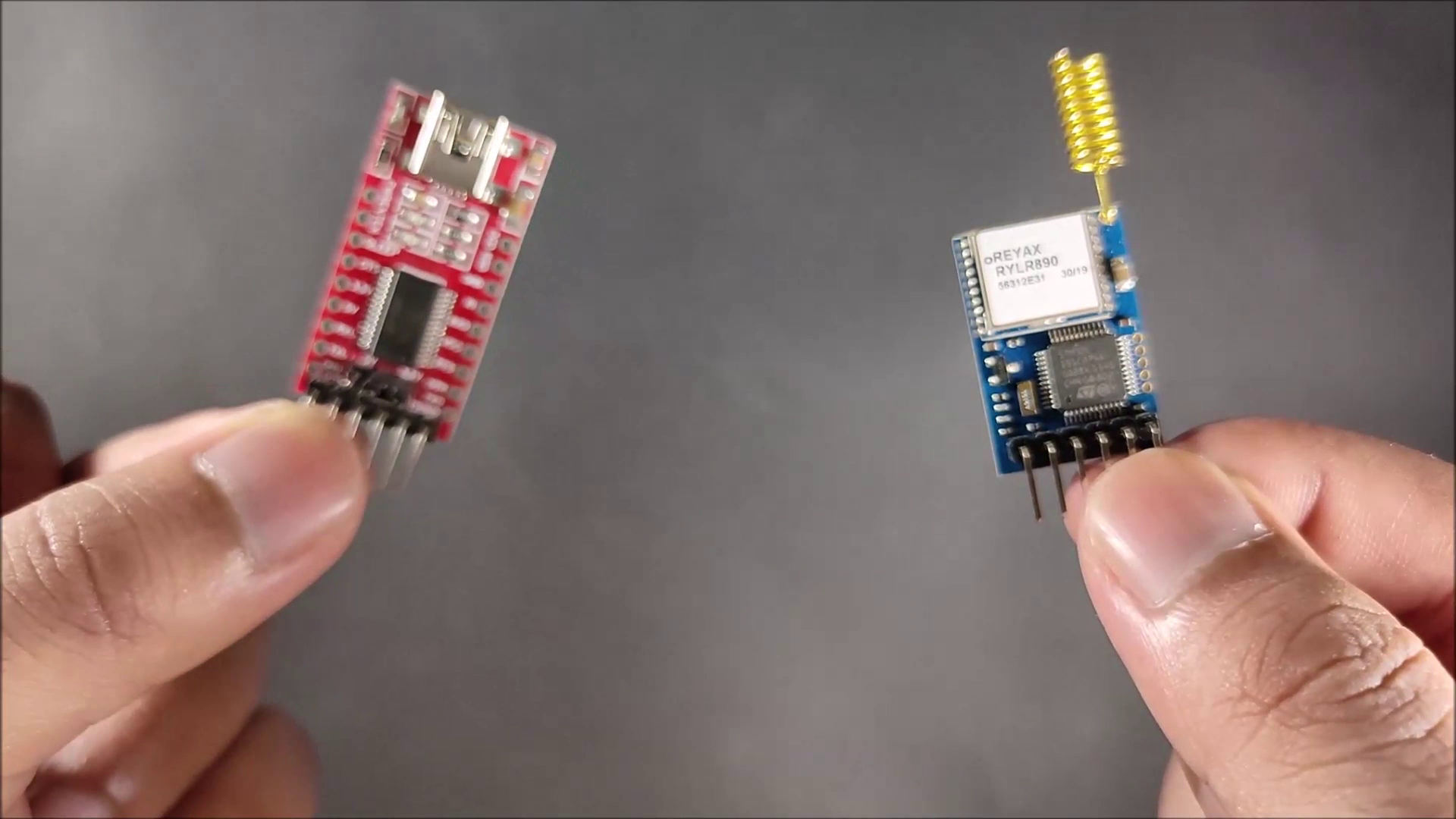
Step 1: Connect Lora Module with PC
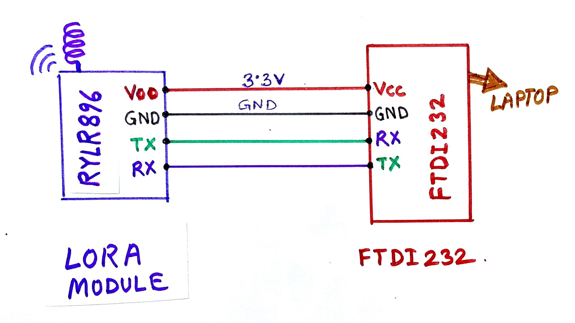
Before connecting the LORA module with Arduino, we have to set some parameters like Address, Band for the Lora module using AT commands. So we need to connect the Lora Module with USB to serial interface board as per the circuit diagram. So that we can connect the Lora module with Laptop or PC. Here I have used FTDI232 USB to Serial interface board.
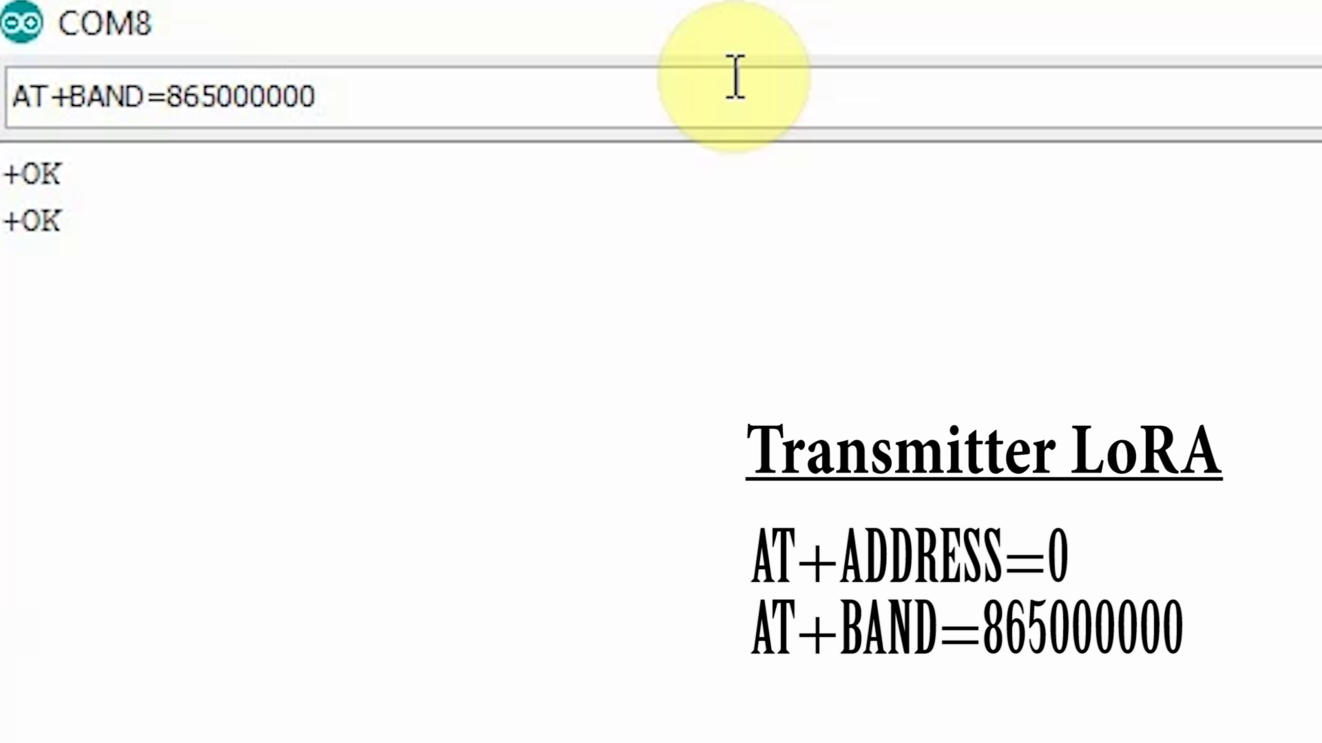
Step 2: Set the Parameter for Transmitter Lora
First Connect the Lora module with laptop. In the Arduino IDE select the PORT Tool–>Port Open the Serial Monitor and set the Brud rate to 115200.
Now we can set the parameters with some basic AT commands.
First, type AT then press enter key. We should get +OK in the serial monitor. Then type AT+ADDRESS=0 to set the address to 0 for transmitter Lora. Then type AT+BAND=865000000 to set the band 865MHz. The frequency band for LoRa Technology in my country is 865 MHz to 867 MHz. You have to set the band as per your country. You can google it to know the band for your country. The default Network id is 0. so we will not change it for this Lora project.
Step 3: Set the Parameter for Receiving Lora
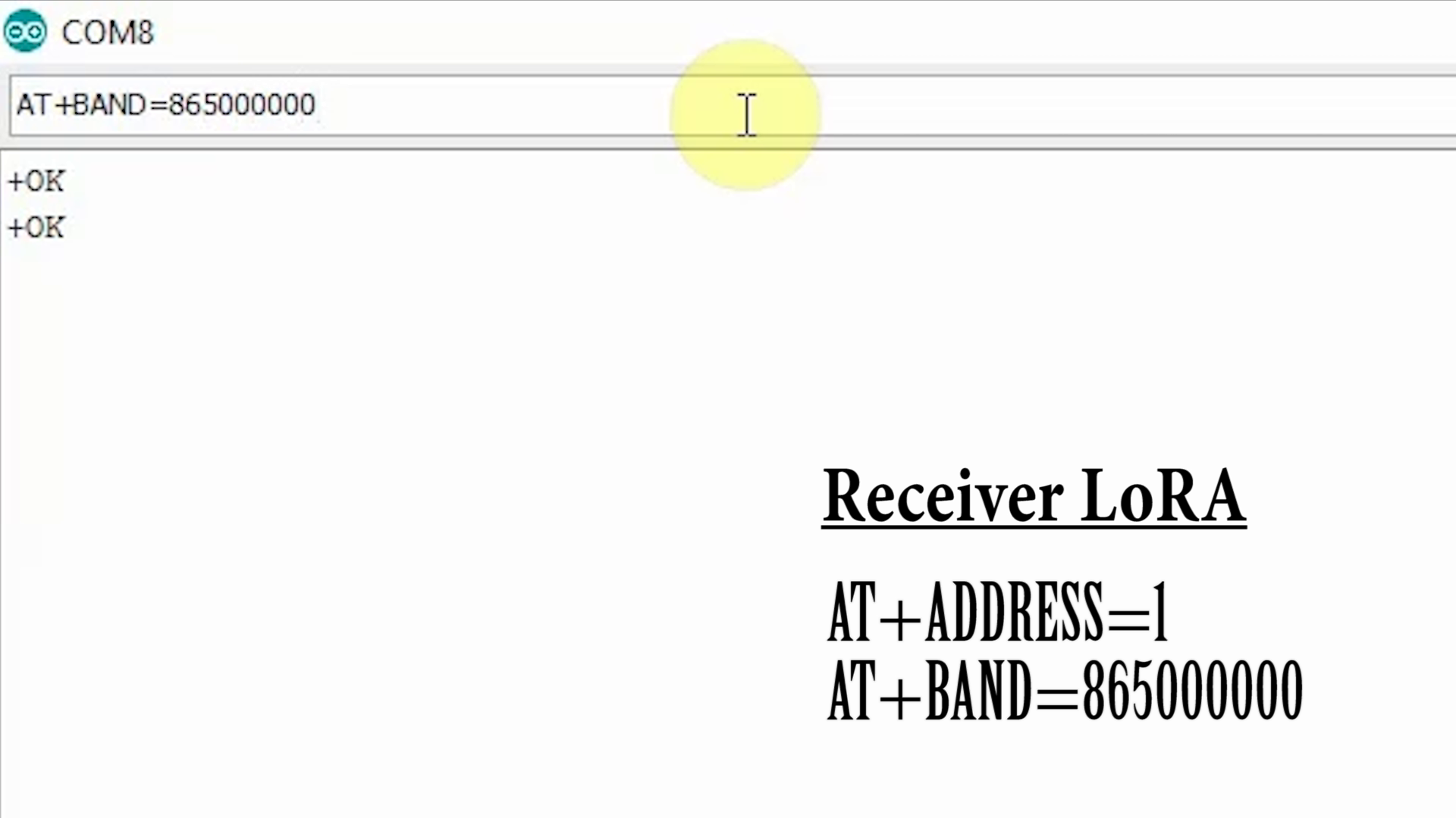
In a similar way, we have to set the parameters for the receiving Lora module
First, type AT then press enter key. We should get +OK in the serial monitor.
Then type AT+ADDRESS=1 to set the address to 1 for receiving Lora.
Then type AT+BAND=865000000 to set the band 865MHz. You can google it to know the band for your country.
The default Network id is 0. so we will not change it for this Lora project.
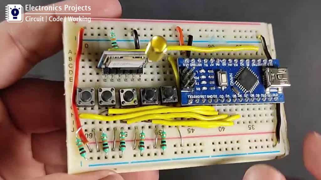
Step 4: Transmitter LoRa Arduino Circuit
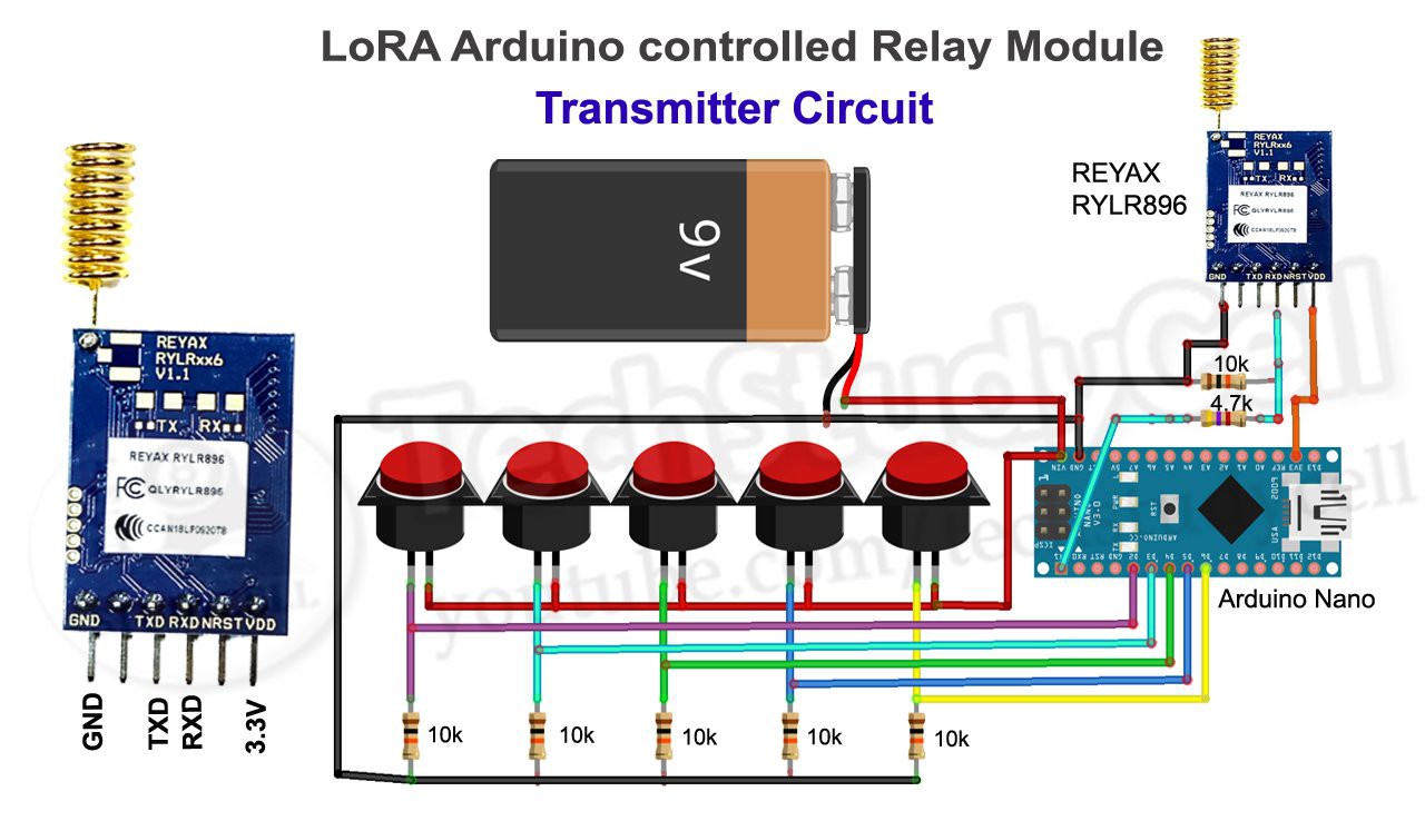
In the transmitter Lora circuit, we have connected the transmitter Lora module with Arduino Nano as per the circuit diagram.
In the Transmitter Lora circuit, 5 push buttons are connected with Arduino digital pin D2, D3, D4, D5, D6. Whenever we press any push-button, the signal sent to receiving the Lora module to turn on or off the respective relay.
Here I have made a voltage divider with two resistors 4.7k and 10k to drop down 5v logic level to 3.3v logic level. Arduino can send the signal at 5v logic level but the Lora module RYLR896 can only receive the signal at 3.3v logic level. So we have connected the voltage divider between Arduino TX pin and Lora RYLR896 RX pin.
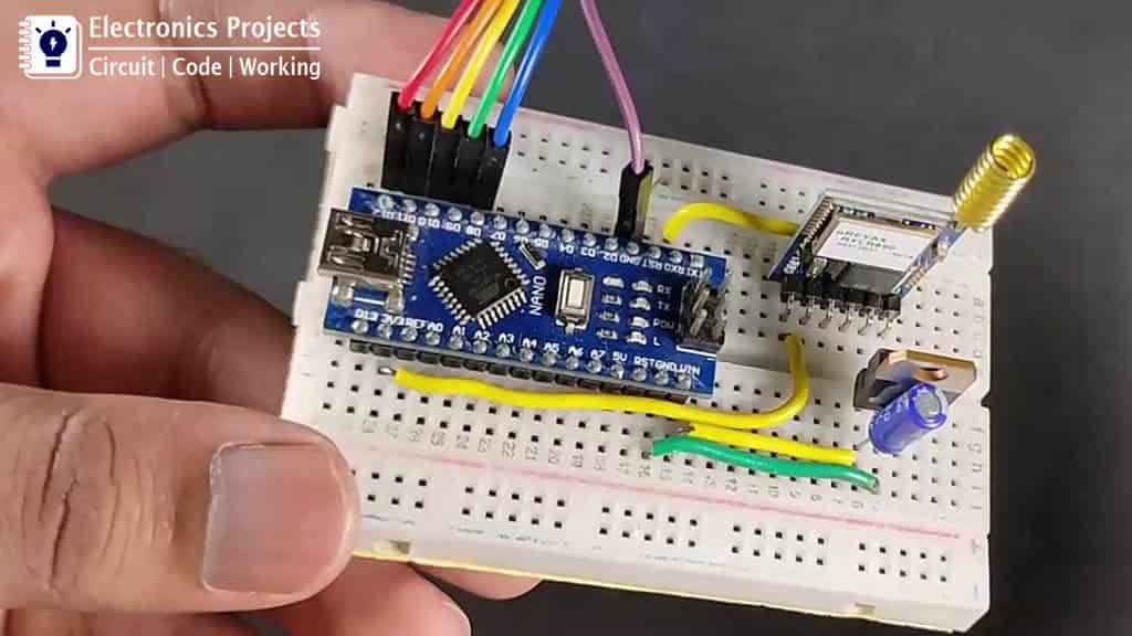
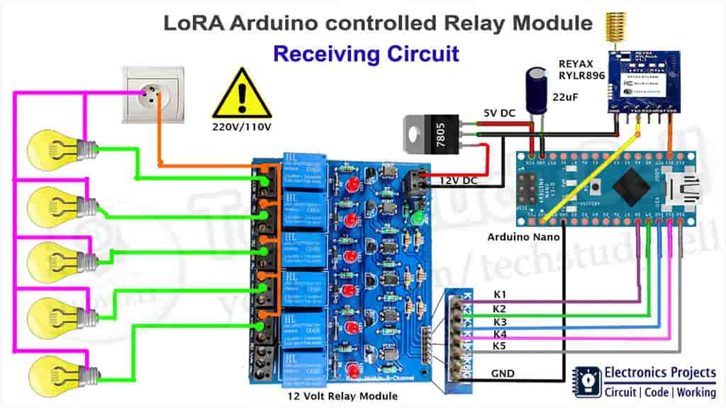
Step 5: Receiving LoRa Arduino Circuit
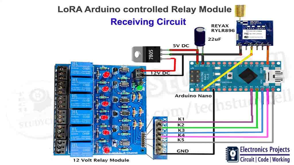
I have connected the receiving Lora module with Arduino Nano as per the receiving Lora circuit diagram.
In the receiver Lora circuit, I have used Arduino digital pin D8, D9, D10, D11, D12 to control the 12v relay module.
Here voltage divider is not required as Arduino can receive signal at 3.3v logic level from the receiving Lora module RYLR896.
I have used a voltage regulator 7805 (5-volt) to fed 5v supply to the Arduino circuit.
Order the PCB
After downloading the Garber file you can easily order the PCB
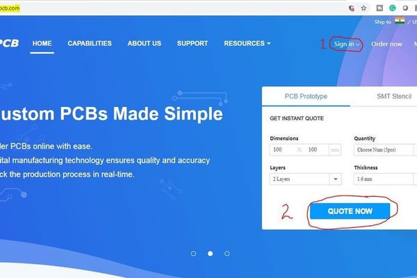
1. Visit https://jlcpcb.com and Sign in / Sign up
2. Click on the QUOTE NOW button.
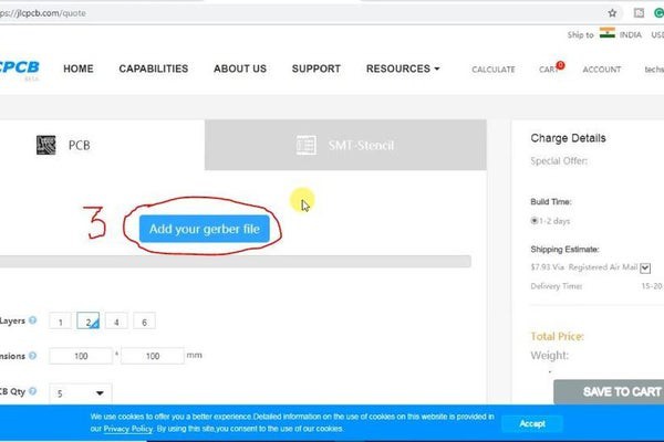
3 Click on the "Add your Gerber file" button. Then browse and select the Gerber file you have downloaded.
Uploading the Gerber File and Set the Parameters
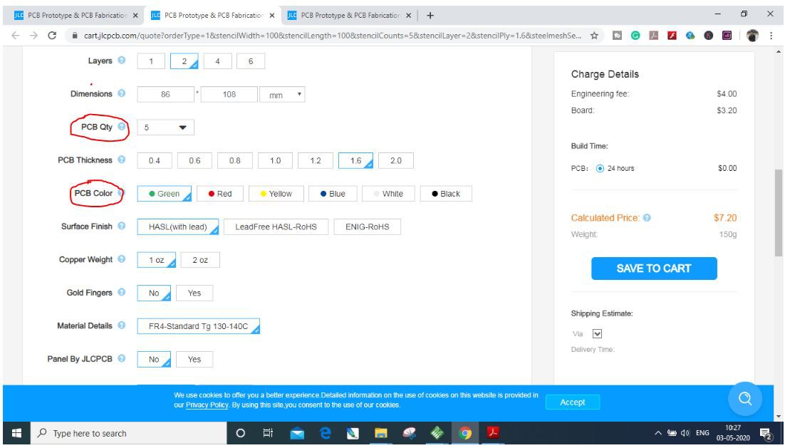
4. Set the required parameter like quantity, PCB color, etc
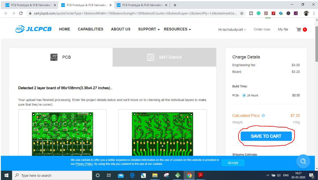
5. After selecting all the Parameters for PCB click on SAVE TO CART button.
Select Shipping Address and Payment Mode
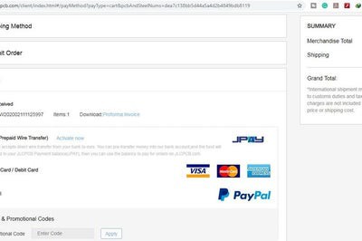
6. Type the Shipping Address.
7. Select the Shipping Method suitable for you.
8. Submit the order and proceed for the payment.
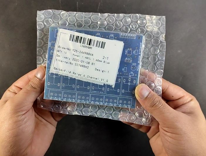
You can also track your order from the JLCPCB.com My PCBs took 2 days to get manufactured and arrived within a week using the DHL delivery option. PCBs were well packed and the quality was really good at this affordable price.
Step 6: Program the both Arduino
Now upload the code for the transmitter and receiver Lora Arduino circuit.
I have explained both the Arduino code in the related video. I will recommend to watch the video for better understanding.
Download the Arduino sketches for this Lora Arduino project:
https://drive.google.com/uc?export=download&id=1jA0Hf32pvWQ6rXFnW1uiHWMEewrxOvKr
Step 8: Connect the Home Appliances
Now we will connect the 5 home appliances with the 12v relay module as per the circuit diagram.
Please take proper safety precautions while connecting 110v or 230v load with the relay module.
Step 9: Finally, the Lora Project Is Ready
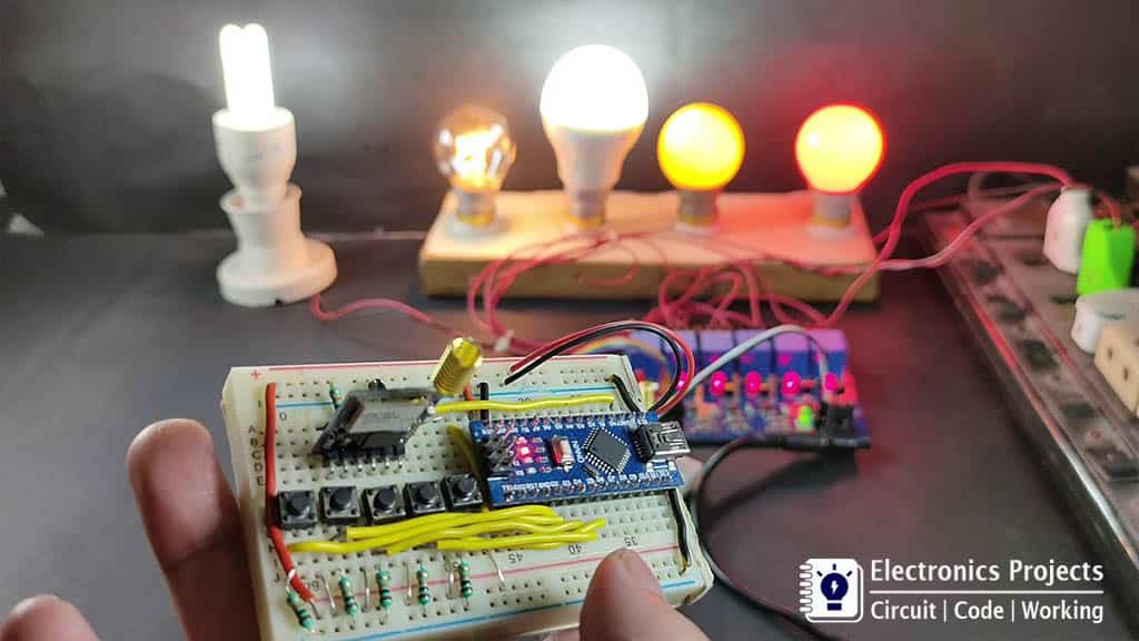
Now we can control the 5 home appliances using the transmitter Lora circuit. Here I have connected 5 230v AC lamps with the relay module. Now if I press any push button, the respective lamp will turn on.
In the rural area with this Arduino Lora project, we can control the high voltage devices from 10 km away without any Bluetooth or WiFi device. So this very useful Arduino project in the rural area.
I Hope, you like this LORA project.
Please do share your feedback on this LoRa project. Thank you for your time.