To make the experience fit your profile, pick a username and tell us what interests you.
We found and based on your interests.
Decided to just jump right onto a repeat of the Hummingbird earrings fixing some of the problems described in the previous log. And a complete shock to no-one, it turned out to be more fiddly than expected. The big change I wanted for this was to have copper on the entire front side, which a mask of the bird cut out. I got close a couple times, except the pour wouldn't come all the way up to the mask. To start I used the svg2shenzen plugin for Inkscape to create the footprint below. It's the same solder mask as before but I've added a F.Cu border all the way around.
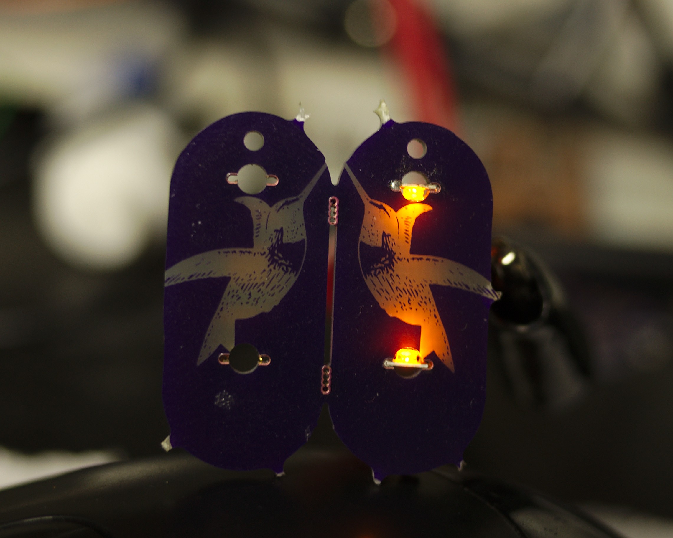
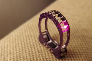
These came out beautifully! I feel like I couldn't be happier with them, even though several improvements are going to be made. First of all, I don't think I ever even bothered thinking about the battery. LEDs are simple right? we light them with coin cells all the time right? Welll., the coin cell I reaaaally wanted to use was this great and tiny LR44 @zakqwy used in the #cyborg ring. What I had forgotten is he uses 2 in series to get 3V. Womp, doesn't matter going to bodge a CR927 clip on there are fix in the next revision, because this certainly deserves another revision.
Additionally I'm going to do a full ground pour on the back (I actually thought I did this....) and a copper silhouette on the front side. The back I hope will reflect light and the front will block the bleed through that can be seen above the lower LED. I may also move the LEDs a bit in an attempt to light up more of the bird.
I also really like this picture as it really shows off how the footprint works, which was quite interesting to solder. As there isn't much copper around it, getting an iron on it was difficult. I ended up smearing solder paste into the slots and on the LED pads and using hot air. This worked out pretty well. The only other real issue I encountered was tiny copper burrs caught in the slot. One can be seen in the lower right slot of the left earring. They were easy enough to pick out and the copper in all of the slots looked fine.
All in all really happy. I'll have the new battery clips early next week and will show off some more complete build pictures.
Alright! The first boards shipped last Friday and as expected arrived here on Monday. Sadly, I missed the Friday Digikey window..... so parts wont' arrive until Wed/Thur at best. Anyhow, the boards look great as expected and of course as soon as I revisited the design files I spotted a mistake. I guess this is expected when you try to last second whack a second ill thought through circuit into a design. Thankfully, the amplifier itself still looks good but I made a huge mistake on the laser diode portion of the circuit. Not only did I misread the datasheet for the worlds cutest laser diode, at some point I accidentally assigned the MOSFET footprint to be a 0603 resistor. Womp.
Two pin transistor eh? Not only that, but the circuit layout is straight up wrong. So I think one of two (or both) things happened, I started with the diode on the high-side and then swapped it with the resistor making it low-side, while also over zealously selecting selecting the MOSFET while assigning the resistor footprints.
Thankfully this is all very bodgeable and taught an important lesson, neither DRC or ERC will catch this kind of mistake. I'm keeping an eye on shipping for now, with a bit of luck it will arrive Thur, with a lot of luck tomorrow when I'll actually have time to build. Regardless next update on this one won't be until next week.
This one got off to such a good start it was almost going to be a two-fer! But as things frequently go that early progress just invited more hacking through the weeds. And as it's getting late on Monday, I figure I'll just push the one I've got and consider myself ahead on next weeks.
Finally sending the #Sprite Wand LED cube off. I did a couple of tweaks before hand to increase its versatility a bit. In addition to the internal connections to mount it on the end of a rod or wire, I added pairs of 4 point connection pads on opposing sides. Four on one side are +/- and Data/Clock In and the opposing side are power and Data/Clock Out. This will allow for cube to cube chainability in at least one direction. I started down a rabbit hole of maximum chainability but had to stop, outside the scope of this, I can easily to another run. Focusing instead on the ascetic portions on this I included edge solder tabs to maximize rigidity, I hope this will help keep the cube shape nice and tight.
This was meant to go out last night but.... yeah. I was drunk, what can I say.
Next up I'm going to revisit #Sprite Wand and have some of these 6 sides LED boxes done in flex. There's going to be a couple tweaks done to enhance chainability but this design should be quick and simple.
As the description says, this is inspired by my partner, who wanting to learn to carve decided to carve one spoon a week. It's been fun to watch the progress of learning the various tools involved and using them for different features or styles. Beyond that, both of us having been laid off in March and the general state of the world, I found myself lacking much motivation to tackle larger projects.
By designing simple circuits, I hope to keep up progress on learning new parts and techniques without having to manage large projects or write extensive firmware. Particularly as I have never formally studied electronics (or anything really...) I want to better learn analog circuitry. With that, I will be kicking this off with a Transimpedance Amplifier that will be part of a beam-break style race timer I've been tinkering on for a couple years. Other projects I've been wanting to do include an Ideal Diode Bridge Rectifier, switching mode power supplies, MPPT solar chargers. Or what ever I can fit in.
Outside of electronics nerdery, my other biggest past-time is bike nerdery. Over the years a group of friends have put on various events, a kind of 'bike games'. During one of these back in 2009 or so we did a street version of a classic track cycling event called the Flying 200. It's a 200 meter sprint were the racer can take a 'running' start, starting as far from the start line as they want. As soon as they cross the line, timer starts and end 200 meters later. Our method of timing with stop watches are walkie-talkies was fun, but not exactly precise. Since then I've made a couple version of line break timers but were always plagued by lack of handling of variable lighting conditions. This inspired the #74xx Hamamatsu S6986 project, which has in turn inspired my design to learn analog electronics better.
The design is largely based on the IRis project on Analog Zoo and a more basic design by IMSAI Guy. I've tried breadboarding out a simple in between design but I just don't have the right parts. I only have older opamps and BPW34 PIN diodes that don't seem to want to work. So I'm sticking closer to the IRis part selection in the hope it'll work better. In addition to the detection circuit I'm including the laser diode on the same board.
This is the circuit so far, I still probably need to do more in the driving circuit, I haven't put much though into that yet. But I suspect the detection circuit should be alright as it's pretty close to the IRis.
https://gitlab.com/morganrallen/52-boards/-/tree/development/Transimpeadance%20Amp
Create an account to leave a comment. Already have an account? Log In.
I am commenting just for the bit of social pressure that someone is watching: You're welcome, and you can do it!
Become a member to follow this project and never miss any updates
 Kevin Arne
 zakqwy
 Jarrett
Sure! Morgan - send me an email please -Drew