 Bogdan
Mostly for small projects I use a combination of Arduino pro mini board with AvrStudio (debugging over Debugwire using not cheap ATATMEL-ICE).
But from some time ATmega328P started to not satisfy me in some aspects (not all pins can be configured as external interrupts, poor peripheral, impossible to remap SPI, I2C on other pins and also expensive debugger).
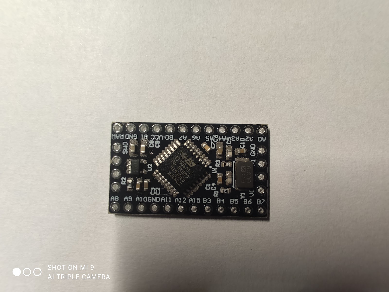
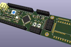
That's why I designed board on STM32 microcontroller that has the same sizes but the reach functionality and cheap debugger.
The MCU of this board is STM32F030K6T6 but it can be compatible with other LQFP32 pack microcontrollers from the STM32 series. For now, tested only with STM32F030K6T6.
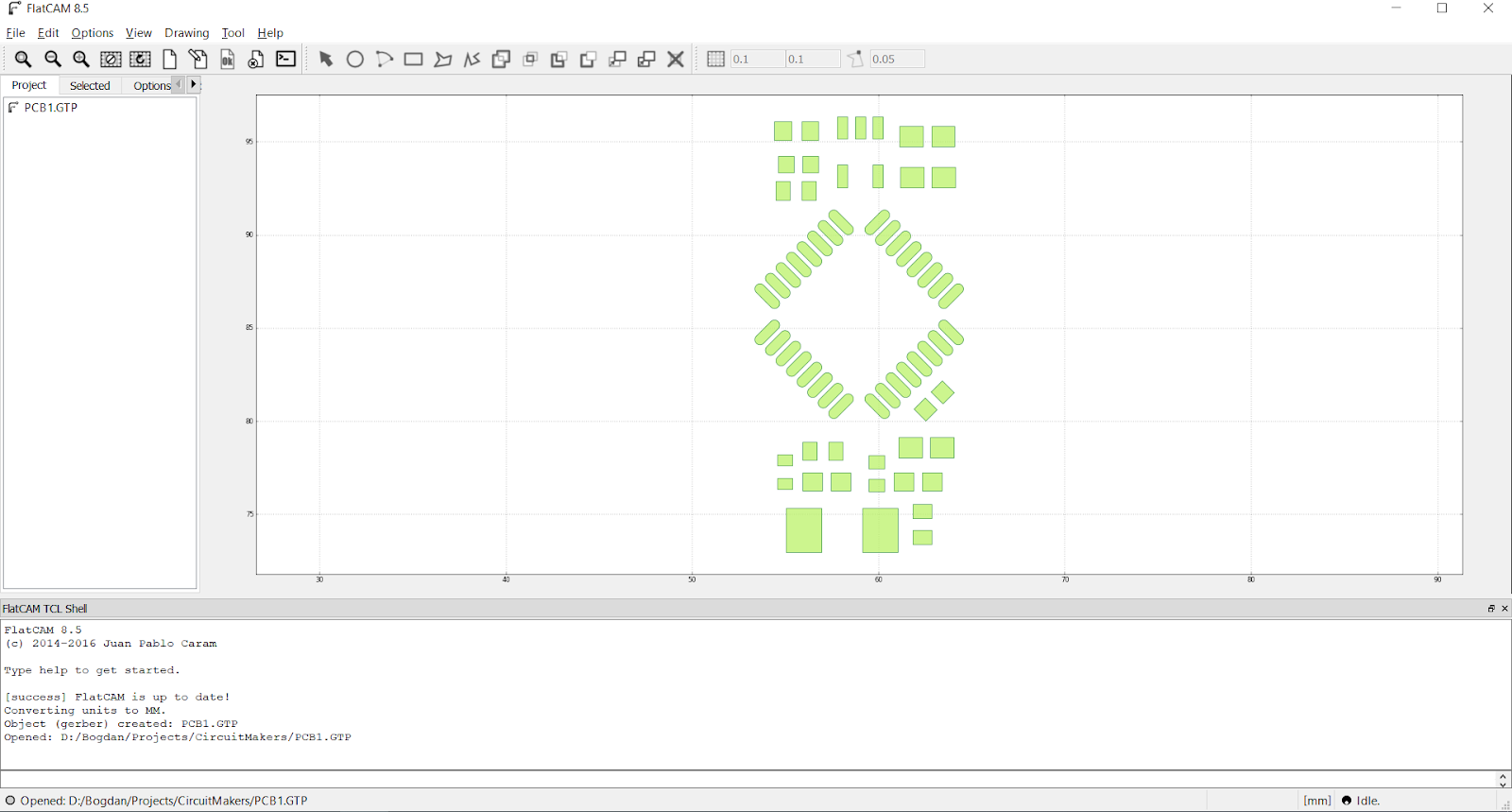
Also during producing that board I learned how to design board, how to order PCB on PCBWay China manufacturer, and how to make at home on the cheap CNC router the stencil for easy soldering components. It was a really interesting experience.
For designing schematic and board used a free tool CircuitMaker.
The workspace with all documents STM32FPromini .
Write and compile firmware for this board you can using STM32CubeIDE.
Program and debug using STLink, STlink from Discovery or any China clones.

 After that firmly apply the paste.
 After that, we will get PCB with solder paste on it.
 Now solder components using a solder station hot air.
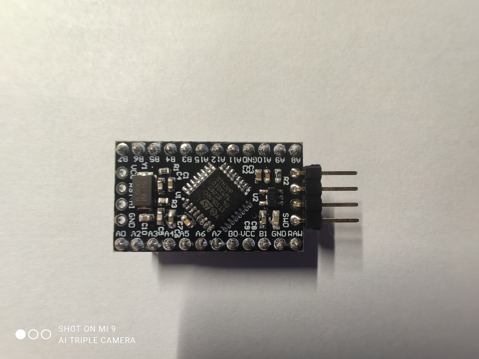
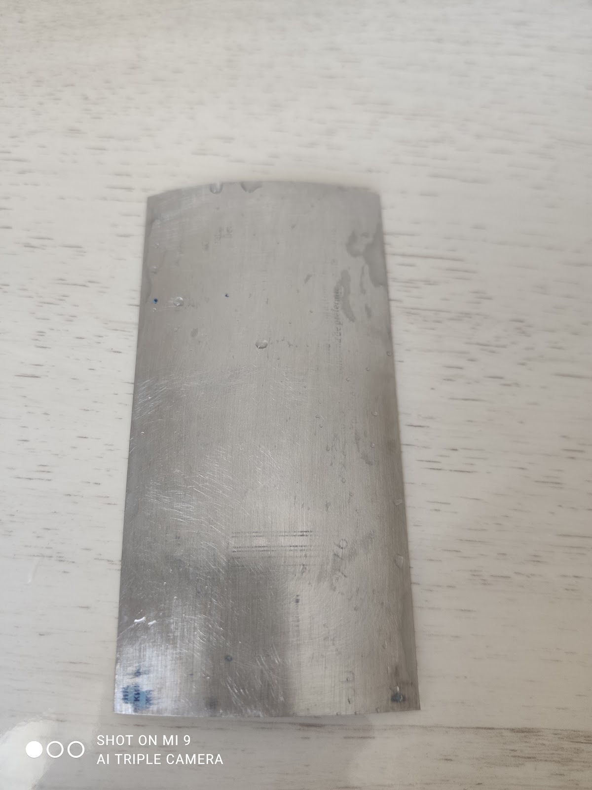
 Using the Iron straighten the sheet.
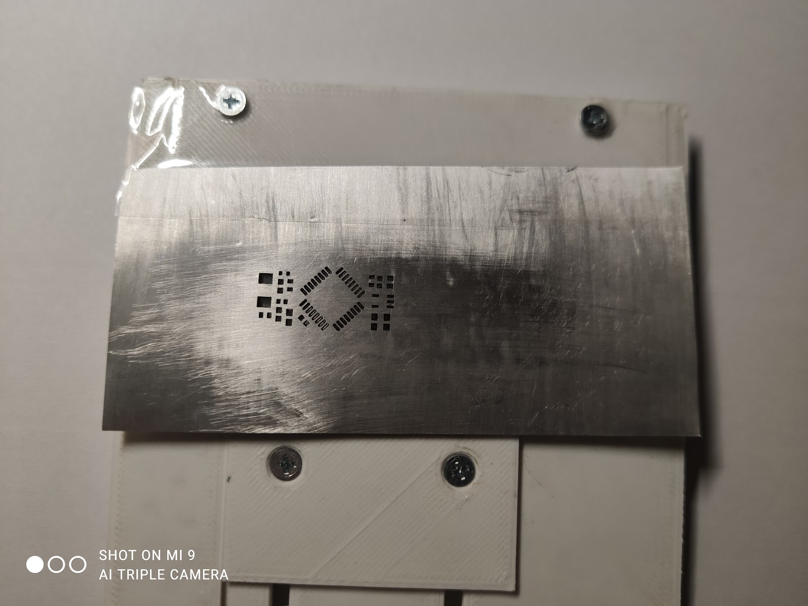
 Mount clean sheet of aluminum in CNC.
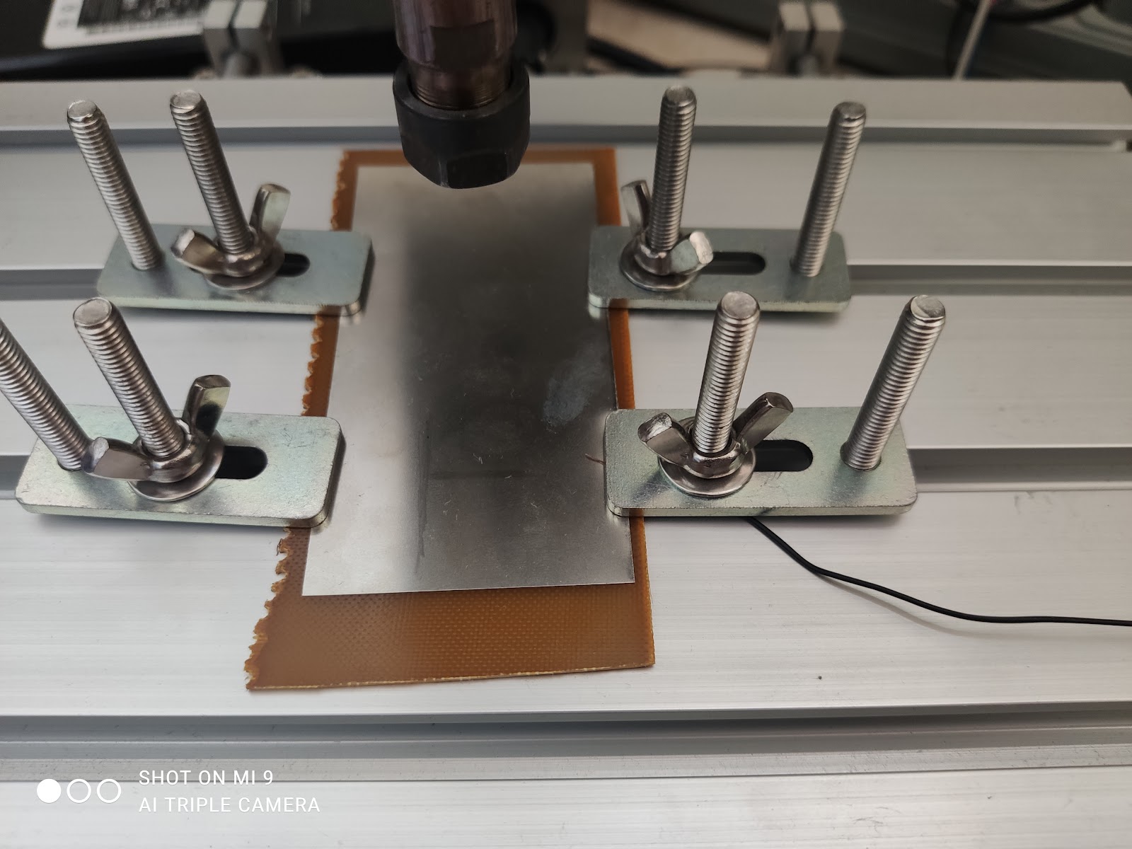

 After cutting we will get aluminum stencil.


 Flavio
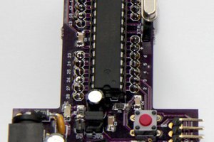
 Andrew Retallack
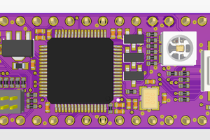
 STAR
STAR
 Kelvin Brammer
What toolchain are you using for these?