I built this handheld about a year ago based on Anthony DiGirolamo’s awesome concept of an RPi handheld and his great thumb keyboard:
https://www.thingiverse.com/thing:3209958
https://hackaday.io/project/162281-teensy-thumb-keyboard
Since I own lots of rechargeable batteries of different kinds I did not opt for Anthony’s suggestion to install a LiPo battery. Instead, I decided to include a StromPi power supply board below the HyperPixel touch screen (the RPi's I2C bus remains accessible via a small cable). That way, the handheld can be powered by almost anything delivering up to 61 volts DC. This decision made the whole RPi sandwich a lot thicker, of course, so there is plenty of space below the thumb keyboard. I thought I might squeeze a microcontroller, a small breadboard and a small OLED display into the housing. That way, a short USB cable is sufficient to connect the RPi to the included MCU, and programs can be tested immediately with visual feedback on the second screen. A nice possibility to tinker and learn something, I thought, for example during tight business trips that do not allow for any real spare time activity while sitting in trains and dull hotel rooms (well, Corona changed things a bit - not so many business trips anymore...).
The setup uses Anthony’s original 3D print files for the keys and the keyboard face plate as well as his PCB, which is powered from and connected to the USB "debug" pads
on the flip side of the RPi 3. I really like the layout, so I just swapped Z and Y for German language use and added umlauts on the FN layer as well as PC function keys, e.g. the rather important F11. Hint: Do *not* print
the face plate with a material that shrinks - I did on first attempt (using ABS), but the seemingly tiny deviations in dimensions make the keyboard utterly unreliable because the keys touch the switches below just slightly
off the necessary position. This is delicate, and Anthony's model is obviously designed with sub-millimeter precision.
The simple printed key labels are somewhat in danger to come off - but so far they haven't, fulfill their task and do not interfere with typing at all.
The entire hardware is mounted on two combined standard size perforated boards for sturdiness independent of the surrounding case. I designed a rather angular housing, but it offers two levels of accessibility: First, there’s a removable cover that reveals just the MCU and the tiny breadboard as well as the OLED and the RPi's I2C cable. But to access all internals except the RPi stack the whole lower part of the housing can easily be slipped off. Below the keyboard there’s even more leftover space that may contain a little box with electronics parts, for example.
The MCU I’ve currently installed is an Adafruit Feather M0 with RFM69 module - quite capable for its size (well, meanwhile there's something called the Teensy 4.0, of course...) and suitable for C(++) code as well as CircuitPython. The radio module in this self-sustained setup makes for a convenient test receiver when working with wireless communications.
As you can see on the photos I included several small slide switches: One allows to cut off the power supply for the keyboard's Teensy 3.2 - useful if one needs to reset the Teensy or to power it independently if necessary. A second switch is the power switch for the RPi when connected to a battery via the clunky looking vertical white plug. I like this sort of plug which is originally intended for halogen lighting setups. It's impossible to accidentally reverse polarity, it stays plugged reliably even with rough handling and is nonetheless easy to unplug again. I've soldered several adapter cables for different kinds of batteries. When using this plug, the MCU may be powered without any USB connection to the RPi. There's a third switch for this purpose hidden within the case leading to a separate voltage regulator. Powering the device via the...
Read more »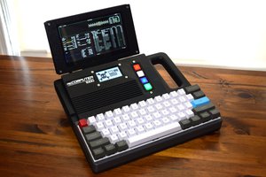
 Tom Nardi
 RasmusB
 Richard