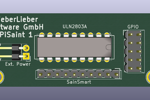
KiCad 5 even provided the Raspberry Pi template with the mounting holes and slots for camera and display cables. The only functional change was to bring out the second output from the DS2406, which will allow a second solid-state relay to be controlled.
Pins on the RJ-45 connector are combined the same way as they are within Ethernet cables, with the first pin of the pair carrying a signal and the second pin of the pair tied to ground:
- 1 & 2: I2C data
- 3 & 6: 1-Wire data
- 4 & 5: 5V power
- 7 & 8: I2C clock
Note that this arrangement allows you to use 4-wire phone cord (wired straight through, not rollover as in most off-the-shelf cord) for 1-Wire, while any network cable can carry I2C as well as 1-Wire.
This board implements 5V I2C and 1-Wire. Level shifters knock the signals down to 3.3V for the Raspberry Pi.
The two relay outputs provide a 5V signal intended to control solid-state relays. You might get away with a small electromagnetic relay on the first output if you include a snubber diode reverse-biased across the coil, but I wouldn't recommend it. PIOA on the DS2406 can sink up to 80 mA at 5 V; PIOB can sink up to 25 mA.
The barrel connector accepts regulated 5V power; it passes it along to the Raspberry Pi through the 5V pin on the GPIO header.
To configure Raspbian to use the DS1307, follow the directions at https://learn.adafruit.com/adding-a-real-time-clock-to-raspberry-pi/set-rtc-time.
 Richard Deininger
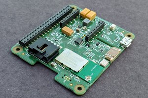
 Rob Crouthamel
 Andrew Mitz