 Greg Duckworth
The mechanical joints necessary for this project must fulfil several requirements of the umbrella project.
Namely:
- Rotate in 1, 2 or 3 axes
- Only move in those axes, no wobble
- Lockable
- Free-moving to fully locked in 1 small motion
- Using only 1 hand
- Range of mounting options
- Multiple threaded holes
- OR counter-bored holes to allow mounting without access to the back of a panel/wall
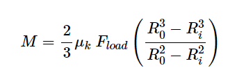
- Friction
- Metal to plastic contact for the sliding elements to prevent binding or galling.
- Cheap
- Less than £20 in materials and accessories
- Time spent is less relevant at this stage
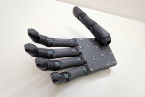
With this list of requirements in mind, I will be designing and making a series of joints and eventually assembling a long arm for the shed.


 Supercell
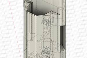
 Andrew Bahls
 agp.cooper
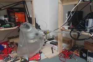
 Zoé
Zoé