 Greg Duckworth
The previously given specification for the joint can be though of as a set of tests which the joint design will be evaluated against. We can make any joint design we like, but if it wobbles then it fails to meet a fundamental requirement. To help to pass the specification tests, we can use some fairly basic design principles to guide our decision making.
So lets start by evaluating the forces and torques on the joint.
I would like the arm to have a reach of 3 meters at full extension and I would the payload to be 2 kg. This is quite a significant extension for such a mass but hopefully we can get somewhere close. The self-weight of the arm is also important: I am going to assume that this is equivalent to another 2 kg at full extension (4 kg total mass, evenly distributed along the arm).
The maximum static torque is experienced by the joint furthest from the load i.e. the joint attached to the wall (Labelled A below)

The torque at A will be 4 kg x 9.81 m/s^2 x 3 m = 117 Nm. We will use the value 120 Nm for ease. This is the value that the joint must be able to comfortably hold. If the joint is able to hold only 120 Nm then it would begin to slip so a factor of safety should be used. In this case a factor of safety of 1.5 feels about right so the joint must be able to hold 180 Nm maximum.
From this site:
We can calculate the holding moment between two discs as follows:
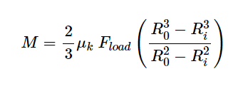
Where M is the moment, µ is the coefficient of friction between the surfaces, F is the force pushing one surface onto the other, Ri is the ID of the disc and Ro is the OD of the disc.
It is difficult to find details of the coefficient of friction for aluminium and Nylon. Tables show the coefficient of friction between Nylon and steel as 0.4 so we will use this value. Ri is 18 mm (0.018 m) and Ro is 25 mm (0.025 m). Friction ref
F is somewhat variable. High force mechanisms are typically difficult to actuate so lower is better. We will find the required force to give a moment of 180 Nm.
This gives a relation of M = 0.008675 * F, (M in Nm and F in N)
The required force to hold 180 Nm is 21 kN.
The bolt that is used to apply the holding force is an M8 which according to Bolt Ref has a minimum ultimate tensile of 29.2 kN (for grade 8.8).
Using a bolt torque to force calculator (Bolt Torque ref) a required torque of 20.2 Nm is calculated.
Discussion
These calculations reveal a lot of the dependency between clamping strategy and the required performance of the underlying components. We could take them further. We could calculate the force that can be exerted by a cam mechanism as they are cheap and easy to come by. We could also investigate the pull-out force that the tapped aluminium could sustain, although I don't think either of these will be hugely useful in my situation.
Instead, I made the first prototype joint and I am going to test it. At the same time I am going to redesign the joint to use a different face contact and use Aluminium-on-Aluminium for the friction surfaces, instead of Nylon-on-Aluminium. I am also doing something I should have done before making the prototype: I am going to run these calculations for several designs to understand the sensitivities involved.
Discussions
Become a Hackaday.io Member
Create an account to leave a comment. Already have an account? Log In.