 Dhairya Parikh
The Solution - in a nutshell

So, the solution to this problem is a bit complex. The aim is to develop a fully functional and smart system using the Particle's Mesh devices so that the elderly people can easily control all the equipment in their house without any help. Here are the parts of the whole system:
- The Main Device: So, the main system powered by the Particle Argon, which is the mesh gateway will be installed in a handheld device that will be worn by the specially-abled person.
- The Furniture Controller: This system will be installed in the movable furniture of the house so it can be controlled by the person. In this project, we are focusing on a small table that has all the medicines of the user. The user can simply control the table by putting the handheld device in motion mode and by his Hand movements (using the accelerometer).
- The Appliance Controller: This sub-system will control the Fans, Lights, Television, etc for the user. So, there will be buttons on the device along with a display. So, by putting the handheld device in Electronic mode, we can select and control the desired device. We will use relays for the actions, that is the turning on or off of the device.
Note: All the sub-systems other than the Handheld device will have a Particle Xenon as the microcontroller in them.
Detailed Solution - Each System in Detail

The System Breakout Diagram
Now, we will be discussing each system in detail with coding, schematics, and some prototype discussion too! So, let's get started!
1. The Handheld Device:
This is the main part of the whole project as this is the component that will connect the user and the whole system. This is powered by a Particle Xenon, a mesh device that has the capability of creating local mesh networks to which a Xenon can connect.
Particle Argon.
Now this small but powerful board will have several peripherals connected to it, which will include :
- A Display (LCD or OLED)
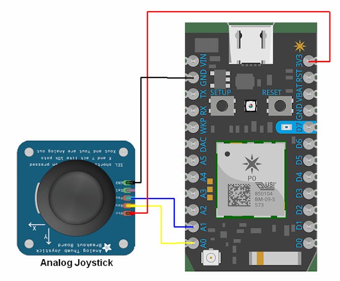
- An Analog Joystick for manual control in motion mode.
- A couple of push-Button switches
- A Sliding Switch for SOS
- An optional Ultrasonic Sensor for Obstacle Detection
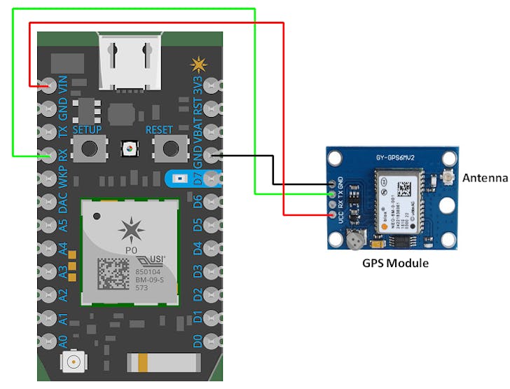
- A GPS module for the real-time location for the android app
- A 3-axis Accelerometer for detecting the state of the user (static, walking or running) and for controlling the medicines table in motion mode.
- An optional Heart Rate sensor for constant Heart rate monitoring of the user along with blood oxygen levels of the user.
- An RGB LED for mode and status indication.
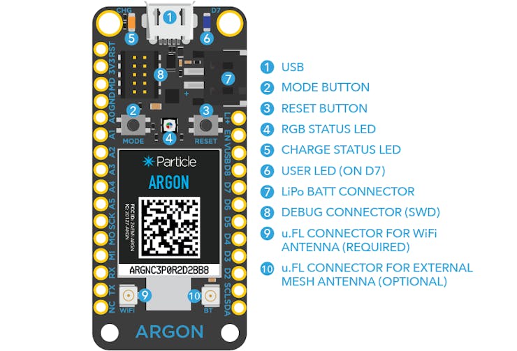
Images of the components:
 Image 1 - Particle Argon and Sensors used
Image 2 - GPS Module
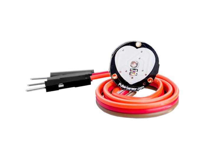
Image 3 - Heart Rate Sensor
Please note that the Particle Argon has enough GPIOs to connect all these devices. But, it would be recommended to use a Seeed Grove shield for Particle Mesh and connect all the required devices using seeed grove sensors. With grove, the connection and usage of these sensors are a lot easier. We will now see some main codes and interfacing.
Codes -
1. For Accelerometer Interfacing: This is the generic or normal sensor interfacing code.

This is for photon, but connections are same for an argon device too.
Code:
#include <math.h>
const int x_out = A1; /* connect x_out of module to A1 of Particle Photon board */
const int y_out = A2; /* connect y_out of module to A2 of Particle Photon board */
const int z_out = A3; /* connect z_out of module to A3 of Particle Photon board */
void setup()
{
Serial.begin(9600);
}
void loop()
{
int x_adc_value, y_adc_value, z_adc_value;
double x_g_value, y_g_value, z_g_value;
double roll, pitch, yaw;
x_adc_value = analogRead(x_out); /* Digital value of voltage on x_out pin */
y_adc_value = analogRead(y_out); /* Digital value of voltage on y_out pin */
z_adc_value = analogRead(z_out); /* Digital value of voltage on z_out pin */
Serial.print("x = ");
Serial.print(x_adc_value);
Serial.print("\t\t");
Serial.print("y = ");
Serial.print(y_adc_value);
Serial.print("\t\t");
Serial.print("z = ");
Serial.print(z_adc_value);
Serial.print("\t\t");   //delay(100);
x_g_value = ( ( ( (double)(x_adc_value * 3.3)/4095) - 1.65 ) / 0.330 ); /* Acceleration in x-direction in g units */
y_g_value = ( ( ( (double)(y_adc_value * 3.3)/4095) - 1.65 ) / 0.330 ); /* Acceleration in y-direction in g units */
z_g_value = ( ( ( (double)(z_adc_value * 3.3)/4095) - 1.80 ) / 0.330 ); /* Acceleration in z-direction in g units */
roll = ( ( (atan2(y_g_value,z_g_value) * 180) / 3.14 ) + 180 ); /* Formula for roll */  pitch = ( ( (atan2(z_g_value,x_g_value) * 180) / 3.14 ) + 180 ); /* Formula for pitch */
Serial.print("Roll = ");
Serial.print(roll);
Serial.print("\t");
Serial.print("Pitch = ");
Serial.print(pitch);
Serial.print("\n\n");
delay(1000);
} 2.GPS Module Interfacing
Here, is the interfacing diagram and code for connecting a GPS module to the Argon.
Code:
#include "Particle-GPS.h"
// ***
// *** Create a Gps instance. The RX an TX pins are connected to
// *** the TX and RX pins on the electron (Serial1).
// ***
Gps _gps = Gps(&Serial1);
// ***
// *** Create a timer that fires every 1 ms to capture
// *** incoming serial port data from the GPS.
// ***
Timer _timer = Timer(1, onSerialData);
void setup()
{
// ***
// *** Initialize the USB Serial for debugging.
// ***
Serial.begin();
Serial.println("Initializing...");
// ***
// *** Initialize the GPS.
// ***
_gps.begin(9600);
// ***
// *** Request that all data be sent.
// ***
_gps.sendCommand(PMTK_SET_NMEA_OUTPUT_ALLDATA);
// ***
// *** Start the timer.
// ***
_timer.start();
}
void onSerialData()
{
_gps.onSerialData();
}
void loop()
{
// ***
// *** This will display the strings received from
// *** the GPS unit. Some may be empty if the GPS
// *** is not set to send all data.
// ***
Serial.print("Data[0] = "); Serial.println(_gps.data[0]);
Serial.print("Data[1] = "); Serial.println(_gps.data[1]);
Serial.print("Data[2] = "); Serial.println(_gps.data[2]);
Serial.print("Data[3] = "); Serial.println(_gps.data[3]);
Serial.print("Data[4] = "); Serial.println(_gps.data[4]);
Serial.print("Data[5] = "); Serial.println(_gps.data[5]);
Serial.print("Data[6] = "); Serial.println(_gps.data[6]);
delay(1000);
}3.Analog Joystick Interfacing
This can be used to control the movement of the medicine table during the motion mode of the device as an alternative to the accelerometer.
Code:
const int joystick_x_pin = A0;
const int joystick_y_pin = A1;
void setup()
{
    Serial.begin(9600);   /* Define baud rate for serial communication */
}
void loop()
 {
    int x_adc_val, y_adc_val;
    float x_volt, y_volt;
    x_adc_val = analogRead(joystick_x_pin);
    y_adc_val = analogRead(joystick_y_pin);
    x_volt = ( ( x_adc_val * 3.3 ) / 4095);  /*Convert digital value to voltage */
    y_volt = ( ( y_adc_val * 3.3 ) / 4095 );  /*Convert digital value to voltage */  Serial.print("X_Voltage = ");
    Serial.print(x_volt);
    Serial.print("\t");
    Serial.print("Y_Voltage = ");
    Serial.println(y_volt);
    delay(100);
}
Now, we will discuss the modes of operation that the device will be programmed for. There will be 3 basic modes and the control will be possible using the various buttons given on the Handheld device.
The Operating Modes:

These are the operating modes
1. Normal Mode:
- This is the normal mode in which the device monitors the heart rate, ultrasonic readings, and accelerometer readings and sends them to the app via Firebase.
- This is the default mode.
- In this mode, all the sensors are operational and we can view the data on the Display.
- It can be activated by a single press of the dedicated Mode Selection Button.
2. Motion Mode:
- This Mode can be activated a pressing the mode selection button 2 times.
- In this mode, we can control the medicine table and other configured furniture using the joystick or just by Hand movements using the readings of the on-chip accelerometer.
- This is basically for controlling the "smart furniture" equipped with wheels and a system controlled by the Particle Xenon.
3. Electronic Mode:
- This Mode can be activated a pressing the mode selection button 3 times.
- This mode is for controlling the electronic appliances like AC, Television, Fans, and lights without having to manually use a switch.
- The controlling part is done a system of relays connected to the Particle Xenon, which is the brain of this sub-system.
Hence, this is the Handheld system, the main component of the system which will help the person with the disability to gain control of the devices and equipment around him.
2. The Furniture Control System
So, this system will have the following components:
- Particle Xenon
- Motors for movement
- Wheels
- Motor Driver L293D or 298
- LiPo Battery
- Potentiometer for Speed control
So, here is a schematic diagram of the system.
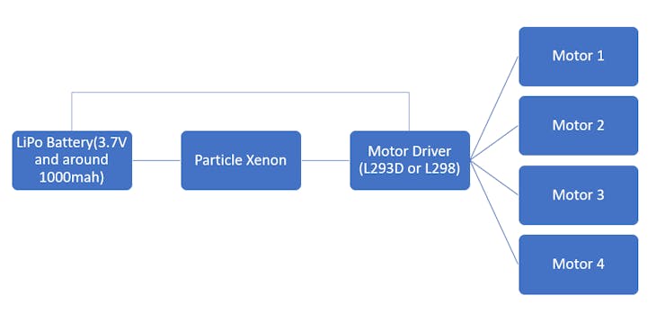
Flow Diagram Schematic
This system takes in the input from the Argon on the user's hand via the mesh network, converts it to movement codes using the Xenon and controls the motors accordingly using the motor driver board.
Now, let's get into some interfacing and coding, the fun part!!
Coding and Interfacing
Please note that all the interfacing diagrams are shown for photon as the Fritzing software doesn't have the Argon board for schematic drawings. But, the procedure would be the same for Argon or Xenon.
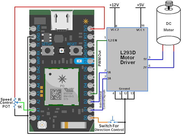
Motor Driver interfacing
Code:
const int pot_input = A1;
bool d1 = HIGH;
bool d2 = LOW;
void setup()
{
    pinMode(1, OUTPUT);  /* Motor control pin 1 */
    pinMode(2, OUTPUT);  /* Motor control pin 2 */
    pinMode(3, OUTPUT);  /* PWM pin for Speed Control */
    pinMode(0, INPUT_PULLUP);  /* Interrupt pin for direction control */
    attachInterrupt(2, motor, FALLING);  /* Interrupt on falling edge on pin 2 */
}
void loop()
{
    int pwm_adc;
    pwm_adc = analogRead(A1); /* Input from Potentiometer for speed control */
    digitalWrite(1,d1);
    digitalWrite(2,d2);
    analogWrite(3, pwm_adc / 16);
}
void motor()
{
    d1 = !d1;
    d2 = !d2;
    delay(200);
}
This code will control the speed and rotational direction of the DC motor using Particle Xenon. We can implement the same, the only change will be that we will take the analog input data of the joystick and change the direction accordingly.
3. The Electronic Appliance Control System
This is the 3rd sub-system which will be controlling all the electronic AC equipment in the system. This will be deployed on each house switchboard so that we can control the devices with the help of our handheld device.
For this, we will have a Xenon in this system too, which will be connected to our Argon via the mesh network. To know more about the particle mesh networks, just visit this Hackster project made by Arduino "Having 11" guy.
This will have a very similar schematic flow chart to the above system.
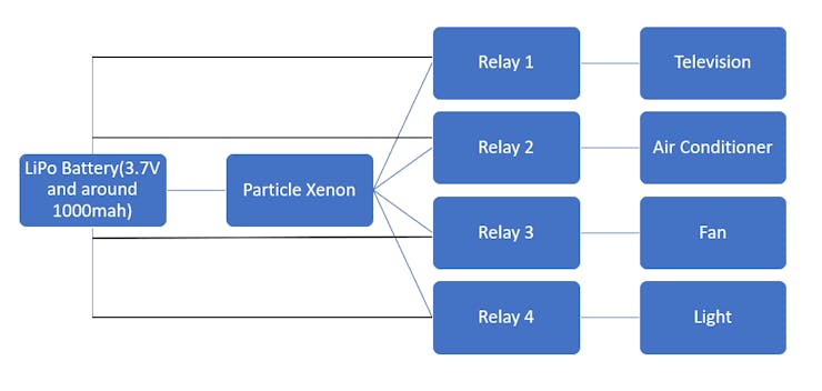
System Schematic Flow Chart
Now, this system works as follows:
1. When the handheld device goes to electronic mode, it is connected to this system via the mesh network.
2. Now, the display on the handheld device shows the status of certain devices that are a part of the network, along with their current status.
3. There are 2 buttons on the handheld device, one for appliance selection and the other for status change. So, just using 3-4 buttons on the device, we can control a number of devices.
To know more about relay and relay control, just follow this article which explains the interfacing of relays with particle devices.
So, this does conclude the hardware part of the project. Now, let us move towards the software aspects of this project.
Software Part of the Project

Now, we have 3 major software components for this project. But, we will also discuss one very important component in the end too. The 3 major components to discuss are:
1.GoogleFirebase ( or Firestore):

This is the database system that we will be using in this project. This is a very important aspect of our project as this will help us in storing and analyzing the data that we obtain from the handheld device.
Moreover, this also can be an alternative to Mesh networking if we would want to change our choice of the microcontroller (for example, to esp32). This will help connect the different systems powered by the esp32. The reason to use Particle is that it provides its very own cloud service for free! We will just use the Firebase for Android application integration and for data storage.
Now, please have a look at my old projects to know more about firebase integration to an android application. The link to the project is given below:
UQM - The Urban Quality Monitoring Device
This project will get you started with firebase and also help you to integrate it with an android application. We use a Raspberry Pi in that project, but it is, even more, easier to integrate the particle devices as they have a readily available guide to do so from their cloud itself.
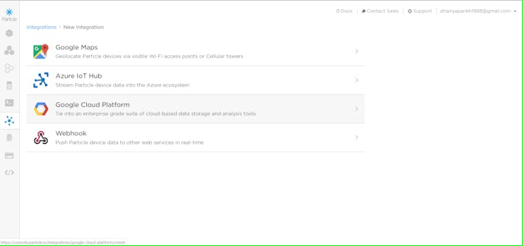
Integrations through the Particle console
The only thing to do is to create a simple web hook that will help you connect to firebase easily through MQTT.
Full step by step tutorial for particle device connection to firebase is given here, which is developed by rickkas7, an active particle community member and a particle device expert.
2. Android Application

Now, we do have the GPS module on our handheld device along with a bunch of sensors that are collecting the data and sending it to firebase.
But, what is the use of this data? Simple! The user's loved ones can easily keep a watch on his activities even if they are away from home. For instance, as elders will be the major target audience for this, their children can easily monitor a number of different parameters like their current state, their heart rate, and even their present location.
A special feature - SOS

Now, this is a special feature which would be absent in many such devices. the handheld device will have an SOS slide switch for emergency situations. So, whenever the user is facing some difficulties in say breathing or he just fell from someplace, he can simply slide this switch and there will be a notification sent to every android application who is registered to this particular handheld device. Note that each handheld device will have a unique id to differentiate them from other devices.
To fully understand how this feature actually works, just go to the project link below wherein I have demonstrated the use of an emergency switch. The SOS switch works in the same way, it gives you a notification and also sends you the current location of the user.
SmartSense - an added sense for the Blind
The android application code is already ready with me, which I developed for a device I developed for the blind people. I have taken inspiration from it and used its design in this project too. The design will be discussed later.
Now, we will discuss a very exciting feature that can take this project to a completely new level.
Special - Tensorflow Lite!!
Yes! it's none other than TensorFlow! With the latest version and advancement in TensorFlow lite, we can now run small models locally. The Particle mesh series have a very powerful ARM chip which gives them this support naturally.
So, we can run machine learning models on-chip! That's awesome, right?
But what will we use the model for in this project?
Well, the possibilities are endless.
1. We can use a model to predict the future state of a user using a regression model that is trained from past stored data.
2. Moreover, we can analyze and predict the probability of a heart attack just using past data.
3. Finally, we can make our movable furniture learn the path that it has to take from source to destination daily. Some self-driving!
For an introduction on Tensorflow Lite for microcontrollers and specifically particle mesh devices, have a look at this article by Brandon Satrom.
So, this wraps up the software part too!
Design
Now, this is a very important aspect of any complete project. Now, designing is a rather difficult job for me as I have very little experience in that field. But, I will give some rough designs for all the sub-systems. So, for the Electronic and Furniture sub-systems, I will be using a Block design, which will be something like this:
only a lot smaller in size, like a cube
Now, coming to the handheld device, I have already developed a similar type of device for Blind people so I will just make some modifications in it and use the same design.
Now, in this device itself, I will add a module similar to the Home Manager, a project developed by one of my fellow Hacksterer, Balaz Simon. Thank you to him for that wonderful and compact design. The only change would be the use of Particle Argon (probably headless) instead of the Maxim board that he used.
I am currently working on this design only so that I can fit the whole system in this enclosure itself.
So, this wraps us the Design part too!
Please view the final design prototype images in the top section.
Conclusion
Hence, this is all about the system we will be developing. A number of things are already ready for deployment. All that is left is to integrate everything to make it into one fully operational system.
If you like this project, do follow me for more such content and do not forget to like this one. Please feel free to comment below any doubts that you have or just message me personally.
Adios!