 Coders' Cafe
Menopause, also known as the climacteric, is the time in most women's lives when menstrual periods stop permanently, and they are no longer able to bear children. Menopause typically occurs between 49 and 52 years of age. Medical professionals often define menopause as having occurred when a woman has not had any menstrual bleeding for a year. It may also be defined by a natural decline in reproductive hormone production by the ovaries when a woman reaches her 40s or 50s. The whole menopause stages can be divided into 4 as
1. Premenopause
2. Perimenopause
3. Menopause
4. Postmenopause
We are not very much interested in other phases of Menopause except perimenopause, as they are silent. Contrarily perimenopause is a noticeable phase with so many symptoms and physical changes. Recent studies show that many of the symptoms are undetected as menopausal symptoms and a majority of women are unwilling to disclose their symptoms even to personal physicians and this makes the situation worse.
As Menopause is a natural process the treatments are focussed on symptomatic relief. One of the most popular treatments available is 'Hormone Replacement Therapy (HRT)' which is not much appreciated due to a number of reasons. There comes the importance of technological solutions for symptomatic relief. Even if there are so many possibilities of technological solutions, it still seems to be an unexplored arena.
So we here present Menesto which is a smart vest for women undergoing menopause, capable of solving some of the predominant menopausal symptoms.
Features
1. Low cost
2. Adaptive
3. Intelligent cooling
4. Auto and Manual temperature settings
5. Instant temperature control
6. Hydration assistance
7. Panic assistance
8. Rechargeable
9. Companion app
10. Covers larger cooling area compared with wearable bands.
Symptoms And Solutions
1. Hot Flashes
Hot flashes are the most common symptom of the climacteric. The symptoms are characteristic of a heat-dissipation response and consist of sweating on the face, neck, and chest, as well as peripheral vasodilation. Researches indicate that the change in skin temperature during a hot flash can be as small as 0.5 ◦C or as much as 5.0 ◦C (Kronenberg F, 1987). Even if there is a noticeable change in skin temperature, temperature alone is not a sufficient parameter to detect hot flash. The temperature along with humidity forms a good parameter to detect hot flashes.
Solution :
Relative humidity and temperature (RH/T) sensors tailored on the vest continuously monitor the temperature and humidity variations on the skin. When the temperature and humidity values go above a predetermined threshold value it triggers the cooling unit via Microcontroller. Menesto comes with two temperature settings,
1. Auto Mode
In auto mode, using the data obtained from temperature and humidity sensors the micro-controller itself determines the vest temperature needed to nullify the effect of hot flashes. It uses intelligent decision making, developed from thermodynamic studies.
2. Manual Mode
If the user feels that the decision taken by the micro-controller is not good, then the user can turn off auto mode and manually set the vest temperature from the companion app.
2. Night Sweats
These nighttime hot flashes trigger a sudden feeling of heat, combined with sweating, increased heartbeat, and a spike in blood pressure. Roughly three-quarters of women in perimenopause and menopause experience night sweat.
Solution :
The same solution built for hot flashes.
3. Panic Disorders
In general panic attacks can be frightening. They typically persist for between 10 to 40 minutes, although some only last a matter of seconds. The symptoms of a panic attack include paralyzing terror, dry mouth, hyperventilation, trembling, and rapid heart rate.
The hormones estrogen and progesterone work together to regulate mood. The declining levels of these hormones during the menopause mean that a woman at this stage of life is more susceptible to anxiety and other menopausal symptoms. If anxiety is left untreated or severe it can escalate into panic attacks. Repeated panic attacks are called panic disorder.
Solution :
We include a panic button to the vest, which can be used to alert the family members or friends in case of unbearable panic attacks. Just press and hold the button for 3 seconds and the companion app will send an email alert with current geographic coordinates to a predefined family member or friend.
4. Dizziness
Dizziness, which is “an imprecise term which may refer to a sense of spatial disorientation, the motion of the environment, or lightheadedness” and is often used interchangeably for vertigo, presyncope, disequilibrium.
Dizziness may occur as a result of another menopause symptom such as anxiety or panic attacks. If suffering from these symptoms, breathing and heart rate levels become rapid and unsteady. This change in breathing can disturb the flow of blood and oxygen to the brain, causing dizziness.
Solution :
The same solution built for panic disorders.
5. Symptoms due to dehydration
Our body is at least 75% water and if we neglect our water intake this can cause a whole raft of symptoms that can look suspiciously like menopausal ones, such as
- Joint inflammation and pain
- Mood swings, anxiety/panic attacks, and stress palpitations
- Headaches
- Constipation/Bloating
- Fatigue
- Bladder problems and vaginal dryness
- Night palpitations
Solution :
We have humidity sensors on the vest that continuously monitor the relative skin humidity which can monitor the water loss through the skin. If the relative humidity is in the normal range the companion app will give notifications in fixed intervals of time which will help us to drink 8 glasses of water between 7am and 10pm. If the humidity is slightly more the time interval is reduced and will notify to drink 12 glasses of water. If the humidity is very more than the normal level the app will help us to drink more water to compensate for the loss.
Check out the demo video for a closer look at the application layout.
Logical Flow

Hardware
1. Peltier Units
Peltier units are used in this scenario for cooling the body. These are some of the key factors which I have chosen for building the project.
- Precise temperature control
- Compact Geometric Sizes
- Reliable solid-state operation
- No sound or Vibration
- Less costly
There are different varieties of Peltier units available in the market. Each one has its own specs. Here I have TEC1-12706 with me.
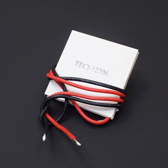
Let's get into the brief working of Peltiers.
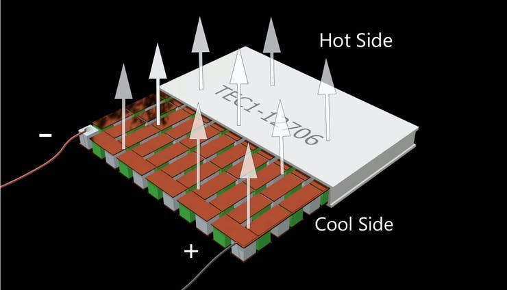
They work by the Peltier effect. Each features an array of P-type and N-type semiconductors. When DC voltage is applied across joined conductors to create an electric current. When the electric current flows through the junctions of the two conductors, heat is removed at one junction, and cooling occurs. So we need to drive the heat deposited at the hot junction with heatsinks and fans. The key point we need to notice that more heat drives the more cooling occurs.
First of all, we need to check the min temperature on the cold side of the Peltier units. We are using two Peltier units powered by ICR18650-22E Li-ion Battery in the 2S2P configuration.I have got these batteries from my old laptops. As I have already mentioned, please operate the Peltier unit with heatsinks and fans.
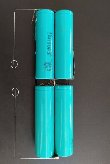
By this configuration, it can provide up to 4400mAh current and about a voltage of 7.4 Volts. One of the facts is that Peltier units are very current hungry. So we won't get more running time.
So we don't have thermometers to check the temperature instead, we hooked up LM35 (temperature sensor) to Arduino.
The value is serially printed as shown below.
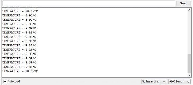
So this is the min temperature we are getting. At a particular voltage, the Peltier units will only give a static temperature. That's not a good ideology at all to proceed with the static temperature, so we need a variant temperature. Here comes the idea of PWM Signals.
2. PWM Signals
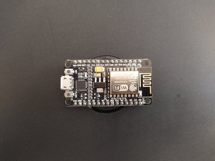
In this scenario, we are using a microcontroller to produce PWM signals. The microcontroller we are using is NodeMcu, which is a low-cost open-source IoT platform. It initially included firmware that runs on the ESP8266 Wi-Fi SoC from Espressif Systems and hardware which was based on the ESP-12 module. We are programming it with the Arduino IDE.
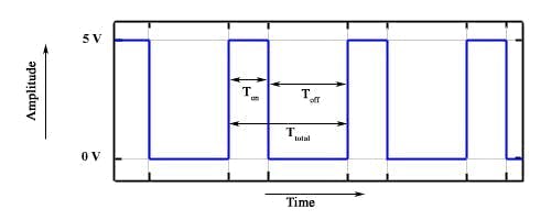
So we can discuss PWM signals. Pulse Width Modulation is a technique for getting analog results with digital means. Digital control is used to create a square wave, a signal switched between on and off. This on-off pattern can simulate voltages in between full-on (3 Volts) and off (0 Volts) by changing the portion of the time the signal spends on versus the time that the signal spends off. The duration of "on time" is called the pulse width. To get varying analog values, you change or modulate, that pulse width. A basic PWM signal is shown in the following figure.
Here are various terms associated with PWM
- On-Time − Duration of time signal is high
- Off-Time − Duration of time signal is low
- Period − It is represented as the sum of on-time and off-time of the PWM signal.
- Duty Cycle − It is represented as the percentage of time signal that remains on during the period of the PWM signal.
To produce a PWM signal on a given pin you need to use the following function:
analogWrite(pin, value);
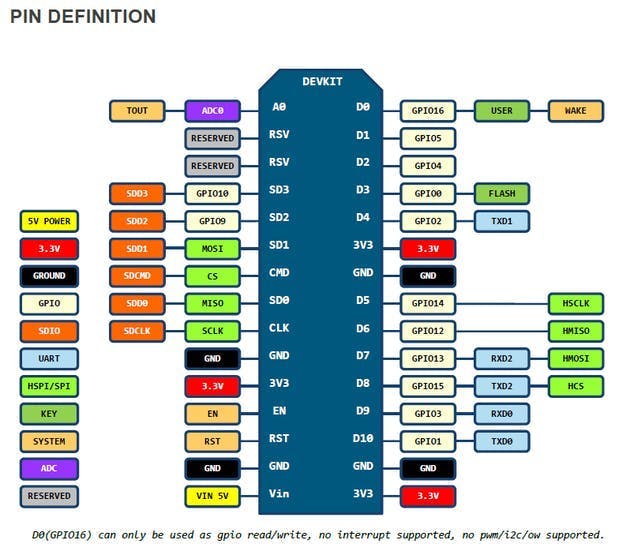
pin : All pins cannot be used for the PWM. These are the PWM pins available in NodeMCU.
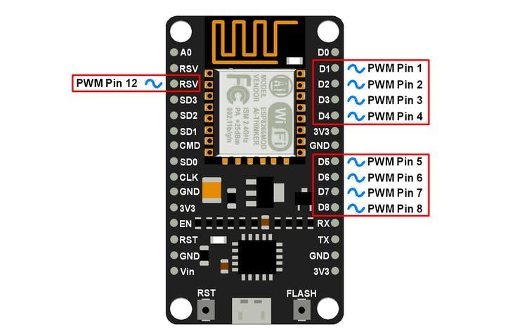
value : should be in a range from 0 to PWMRANGE, which is 1023 by default. When the value is 0, PWM is disabled on that pin. A value of 1023 corresponds to a 100% duty cycle. That is, the higher the PWM value the more cooling occurs. The lower the value, the lesser cooling we get.
So we are able to give a variable potential to Peltier units by PWM signals. But the NodeMcu is a 3.3V microcontroller and it can provide only upto 12mA on its's digital pins. Peltier units require higher voltages and currents to operate. So in this occasion a transistor can act as a digital switch, enabling the NodeMcu to control loads with higher electrical requirements.
There are mainly two varieties of transistors namely BJT(Bipolar Junction Transistors) and FET(Field Effect Transistors). Normally for higher power applications, the FET is suitable. The FET family consists of JFET(Junction FET) and MOSFET(Metallic Oxide Semiconductor FET) members. The Mosfets are widely used for controlling higher loads. If you don't know how MOSFET works, just have a look here.
One of the most important characteristics of MOSFETs is V_GS(Gate-Source Voltage). The potential between gate and source pins must be higher than the max. value listed in the datasheet, for the MOSFET to turn on. For the ordinary MOSFETs, it's higher than 3.3V. So you can't properly drive the MOSFETs with NodeMcu. The better solution is to use a 3.3V logic level MOSFET designed to be interfaced with 3v3 systems.
I don't have logic level MOSFETS. Normal BJT can't drive higher current. That will fry your transistor. Fortunately, I have a Darlington Transistors.
3. TIP122
The TIP122 is a Darlington pair NPN transistor. It functions like a normal NPN transistor, but since it has a Darlington pair inside. It has a good collector current rating of about 5A and a gain of about 1000. It can also withstand about 100V across its Collector-Emitter hence can be used to drive heavy loads.
When we give a PWM signal to the transistor, a small amount of current on the base pin closes a circuit, between the collector and emitter pins. According to the variation in the PWM signals, the current flow between emitter and collector changes.
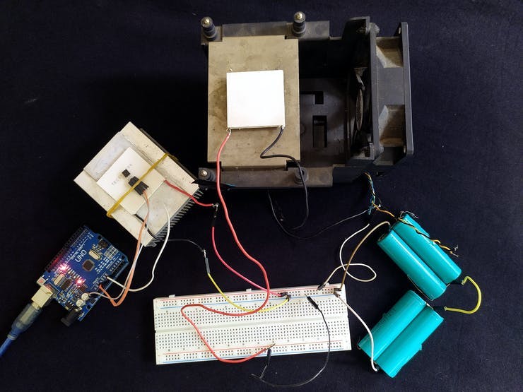
Then we can drive our Peltiers with the transistors via the Microcontroller.
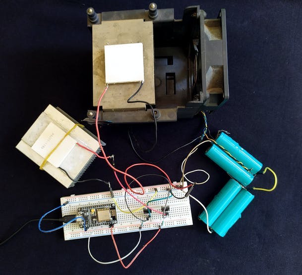
Two Peltier's are driven with separate TIP122 Transistor. As you can see in the picture above, I have powered the NodeMcu with the USB cable. In the final version, it will be powered from the battery pack itself. So it's working fine, we have received temperature variations when the PWM value changes off.
We need to actually sense the skin temperature and humidity to control the cooling unit. So in the next section, we'll talk about our sensors.
4. DHT11 & DS18B20
Our concern is to, not only just sense the temperature & humidity but also giving more accurate readings. First, we proceeded with the project using two DHT11 sensors. It will actually sense both temperature and humidity. But it seems to be poor in accuracy. If you are interested in the working principle of DHT11, just have a look here. Here are the ranges and accuracy of the DHT11
- Humidity Range: 20-90% RH
- Humidity Accuracy: ±5% RH
- Temperature Range: 0-50 °C
- Temperature Accuracy: ±2% °C
In the case of humidity sensing, we don't need that much accuracy because in menopause the humidity varies over a large region. But in the case of temperature sensing, we are replacing one DHT11 with the DS18B20.
DS18B20 is a 1-Wire digital temperature sensor. Reports degrees in Celsius with 9 to 12-bit precision, from -55 to 125 with an accuracy of +/-0.5. Each sensor has a unique 64-Bit Serial number etched into it - allows for a huge number of sensors to be used on one data bus. One of its main specs is 1-Wire interface requires only one port pin for communication. Why we are increasing the accuracy is that the change in skin temperature during a hot flash can be as small as 0.5 ◦C or as much as 5.0 ◦C as I already mentioned.
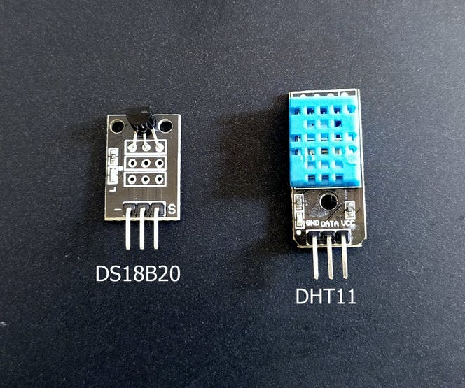
Both of the sensors are modules, so it can be easily tailored on the Vest. In this occasion DHT11 will only sense the humidity while DS18B20 senses the temperature. These are the key factor in determining the cooling and hydration assistance. In future updates, we will increase the precision in temperature and humidity readings.
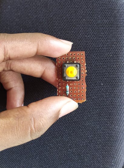
5. PushButton
For making the panic button we are just using a Push Button. The push button is a component that connects two points in a circuit when you press it.
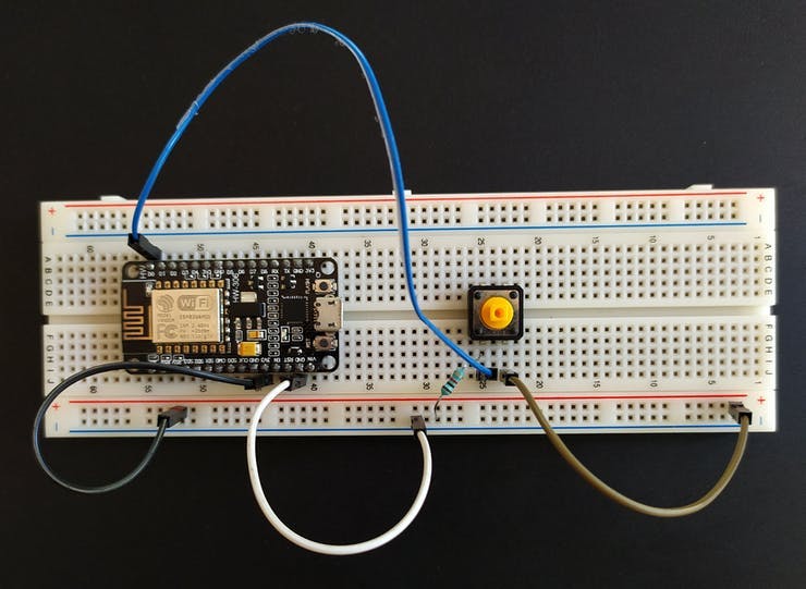
We are using a 1K pull-down resistor to avoid floating.
6. TP4056 Charger Module
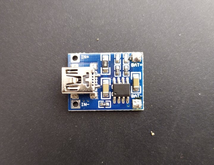
The TP4056 is a complete constant-current/constant-voltage linear charger for single-cell lithium-ion batteries. Its SOP package and low external component count make the TP4056 ideally suited for portable applications. In this case, the power supply is about 7.4V with 4400mAh capacity(2S2P configuration). We can't use TP4056 for charging 2S2P configuration because it only provides 3.7V & current of 1A.
2S Li-ion chargers with BMS(Battery management system) will be the solution for this problem, but due to lockdown, we can't purchase kinds of stuff from the online and offline stores. So we are going with the TP4056 charger module by separately charging 2P configurations. I know it's harder to accept but we don't have any other options. In the next version, we will use the 2S Li-ion charger.
That's all about the hardware.
Software
1. Arduino IDE
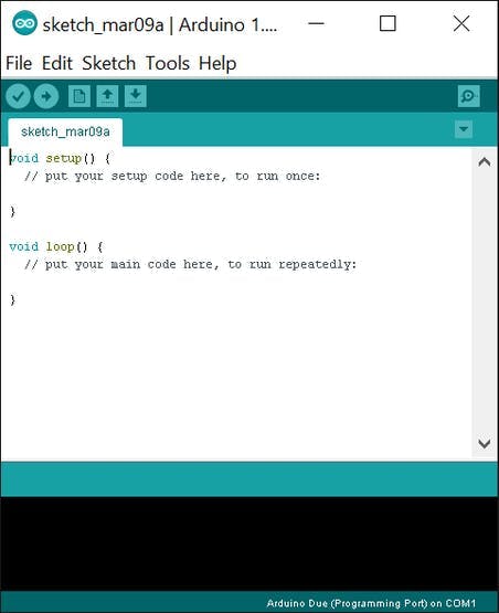
We are programming the NodeMcu with the Arduino IDE. The NodeMcu programming is very easy in Arduino IDE for beginners. If you don't know how to begin programming the NodeMcu with Arduino IDE just have a look here. The complete code for this project is given here.
2. Blynk
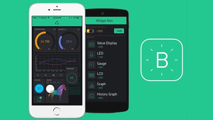
Blynk is a Platform with IOS and Android apps to control Arduino, Raspberry Pi, NodeMcu, and the likes over the Internet. It's a digital dashboard where you can build a graphic interface for your project by simply dragging and dropping widgets. The companion app is built using the Blynk platform. Here we are making a sophisticated app for the vest. Just have a look hereto get started with the Blynk. To start off the project we need widgets.
Widgets are interface modules. Each of them performs a specific input/ output function when communicating with the hardware. There are 4 types of Widgets:
- Controllers - used to send commands that control your hardware
- Displays - used for data visualization from sensors and other sources;
- Notifications - send messages and notifications;
- Interface - widgets to perform certain GUI functions;
- Other - widgets that don’t belong to any category;
Each Widget has its own settings. Some of the Widgets (e.g. Bridge) just enable functionality and they don’t have any settings. The widget we are using in this project.
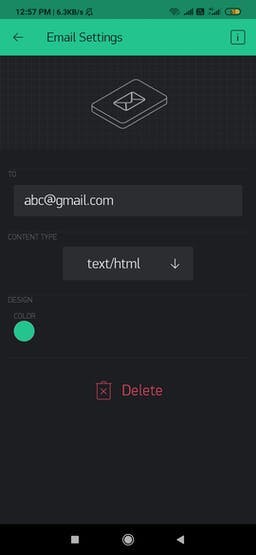
1. Email

Email widget allows you to send email from your hardware to any address. This is used for sending the email to the concerned one when there are panic attacks. In the widget settings, you need only enter your concerned email.
2. Notification

Push Notification widget allows you to send push notification from your hardware to your device. This is for notifying the user, to take water. Check out its settings
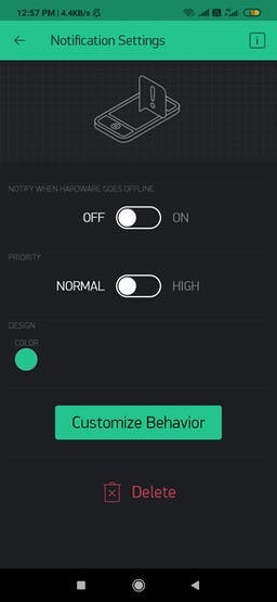
Notification priority is up to the user.
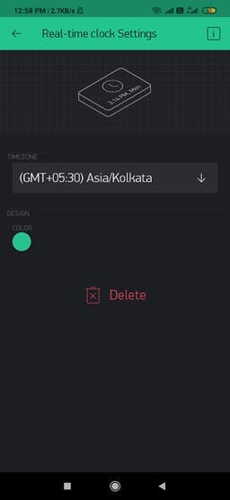
3. Real-time clock
A real-time clock allows you to get time from the server. You can preselect any timezone on UI to get time on hardware in the required locale. No pin required for the RTC widget. This is for setting time in the vest. Have a look at its settings.
4. GPS Stream
Useful for monitoring smartphone location data such as latitude, longitude, altitude, and speed (speed could be often 0). GPS Streaming works in the background. In this case, when the user activates the panic button, the current geographic coordinates will be attached with alert mail via the GPS stream widget. Before getting into its widget settings we need to know about virtual pins.
Blynk can control Digital and Analog I/O Pins on your hardware directly. You don’t even need to write code for it. They can be used to send any data from your microcontroller to the Blynk App and back.
So in the widget settings, we need to specify the virtual pins. The same virtual pin must be specified in the code also otherwise, it won't work. The information such as latitude and longitude is stored in the virtual pin. The picture below shows the widget settings of the GPS Stream.
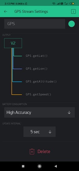
Also, the user can set the accuracy levels and the update intervals.
5. Button

Works in push or switch modes. Allows sending ON and OFF (LOW/HIGH) values. The button sends 1 (HIGH) on press and sends 0 (LOW) on release. This is actually used here for enabling & disabling the Auto cooling feature in the Vest. When this button is enabled, the vest will automatically set temperature in accordance with your body temperature. This also requires a virtual pin. The below image shows it's widget settings.
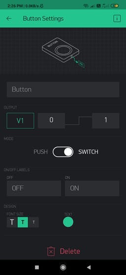
The button can be worked in either in Push or Switch mode. We can also customize the labels of ON/OFF buttons.
6. Slider

Similar to the potentiometer. Allows sending values between in a given MIN/MAX range. This widget is used for setting the temperature manually and this works only if the Auto Cooling button is disabled. We are getting a minimum temperature of about 10 degrees in the cooling unit and the maximum value is of the body temperature(35 degrees) So in the widget settings, we are setting the min value as 10 and the maximum value is 35. When you slide from the left to right, the cooling decreases, and vice versa. In this case, too you need to set the virtual pins. The below image shows the widget settings.
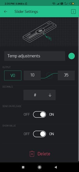
Decimals give you the accuracy in sliding the value.
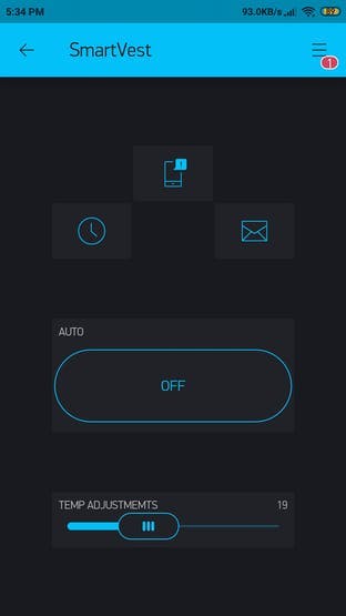
Application Layout
Here is the layout of the application when it opens up.
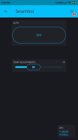
When you scroll down you can see this. To make the user interface attractive, I placed the GPS widget at the bottom of the app.
Actually, this is just a project we have made on the Blynk platform. We are making a dedicated application for the vest in the blynk. Please have a look here to make a standalone app from the blynk.
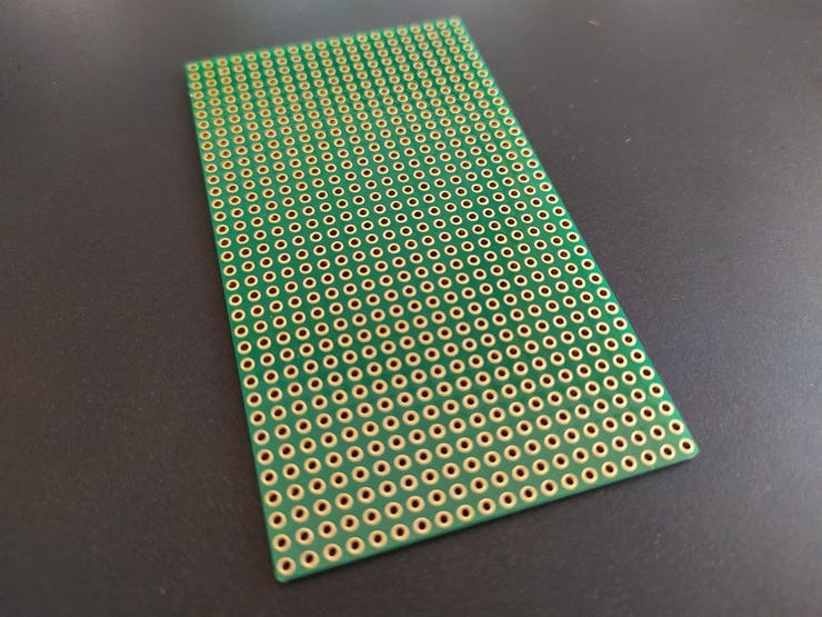
Circuit
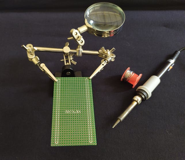
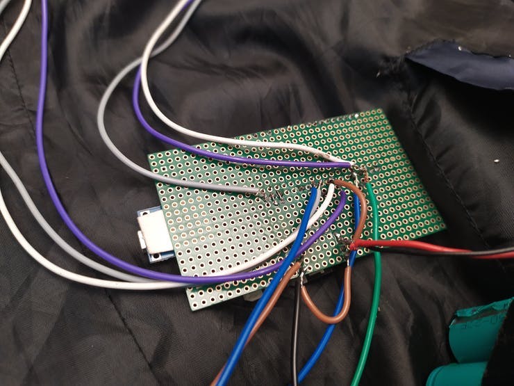
So we can move from the Breadboard to PCB, so it can be easily tailored to the vest. For assembling the components we are using a small green PCB. Only a few components will be in the PCB, remaining will be in the Vest.
Let's start off soldering works by looking at the circuit diagram.
I have placed the components in the PCB. Made female header for the NodeMCU.
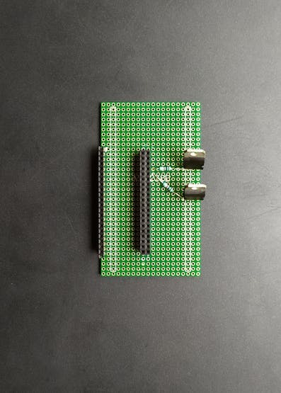
I have also secured some places for the TP4056 charger module in PCB.
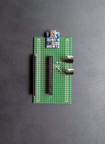
After, NodeMCU is plugged in its Socket.
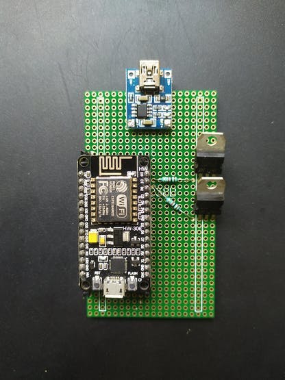
I have cut out a small piece from PCB, then I made my Panic Button Module.
So all the modules are ready, let's go for assembly.
Assembling Components
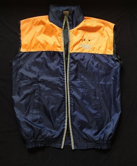
I have an old jacket with me and I repurposed it for making the Smart Vest.
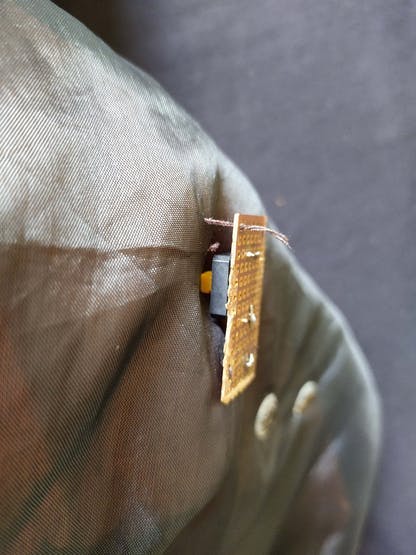
First of all, we are attaching the humidity and temperature sensors on either armpit. We are just sewing the modules on the vest using the needles.
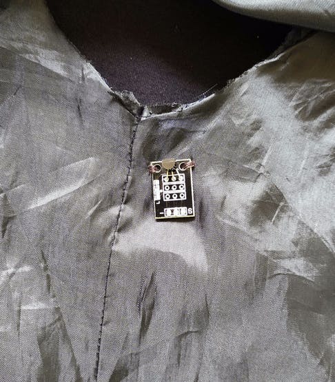
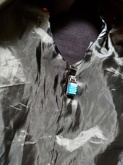
The reason why we are placing sensors on armpits is that the temperature and humidity rise in the skin can be detected properly there. Then we secured the places for the Panic Button Module.
Then I attached the heatsinks and fan to the Peltier units. There will be a slight variation in the min temperature, that's is not a problem at all because it's just a prototype.
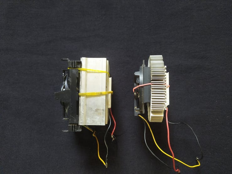
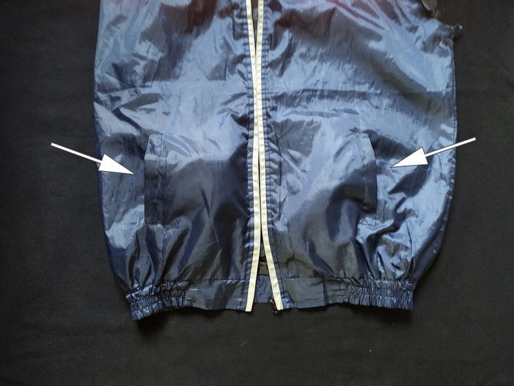
The Peltier units were attached to either side of the front pocket. The cooling side will be faced toward the body. There is a thin conducting layer on the inner side of the vest to spread cooling.
Then we can wire the circuit as per the schematics.
For the sake of convenience, I have clubbed the 2P configurations into 2S2P by tapes.
Then we need to power the Microcontroller with the battery pack. These things are attached to the inner pocket.
So our Smart Vest is ready to use.
Demo Video
Total Cost
Here I am calculating the total cost spent on this project
- 2 * Tec1-12706 with heatsinks and fan - 11.98 $
- NodeMcu - 3.08 $
- 4 * Li-ion Battery(18650) - 5.86 $
- DHT11 - 1.30 $
- DS18B20 - 0.92 $
- 2 * TIP122 - 0.24 $
- PushButton - 0.06 $
- 3 * 1K Resistor - 0.05 $
- Wire - 0.79 $
- Female Header - 0.24 $
- PCB - 0.20 $
- TP4056 Charger Module - 0.39 $
- Old Jacket - 5.00 $
So the total cost is 30.11$.
What in the Future?
- Single custom PCB will be made by including all the modules
- 2S Li-ion charger IC will be used instead of the TP4056 charger module, hence we can charge batteries simultaneously.
- High precision Temperature( ±0.1 accuracy) and Humidity( ±2% RH) sensors will be opted
- The bulky heatsinks and fan will be avoided and we will use a laptop CPU cooling fan with dense copper heatsinks. So the cooling unit can be made compact and weightless.
- The inner layer of the vest will be replaced by the conductive threads.
- The companion app will be made in Android Studio.
- The circuit will be optimized, so we can increase the running time of the vest.
I can guarantee that the Smart Vest will be only cost less than 50$, even though by making all the above future updates.
References
1. Hot flashes: behavioral treatments, mechanisms, and relation to sleep
[ RR Freedman - The American journal of medicine, 2005 - Elsevier ]
2. Thermoregulatory physiology of menopausal hot flashes: a review
[Fredi Kronenberg and John A. Downey - Canadian Journal of Physiology and Pharmacology, 1987 ]
3. Symptoms of the menopause