 Pep3175
Concerning the power supply, I chose an integrated circuit used in the power bank: IP5306.
The purpose of the IC is to manage the charge, discharge and protection of the LiPo battery but also to boost the voltage to 5V. The voltage supplied by the battery varies from 4.2V to ~2.8V depending on its charge. Moreover, this IC allows to drive up to 4 LEDs to indicate the battery charge level.
The CM3+ requires 3 different voltages to operate correctly : 5V, 3.3V and 1.8V. The documentation also mentions a 2.5V voltage but this one is only mandatory for the composite video output which I don't use.
So I start from the 5V voltage and use voltage regulators to obtain the 2 others.
To power the backlight of the screen, I need to power 6 LEDs in series. So I need a higher voltage for this module: ~19V. For that, I use a boost-converter based on the IC PT4103.
For the power supply part, I followed the IP5306 datasheet recommendations and made a first PCB to test the chosen options.
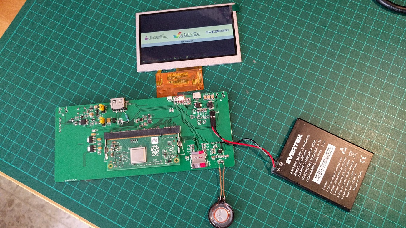
From there came out:
- you have to be careful with the implementation of the screen connector. Yes, on this version, I reversed it... :smile:
- I need a pulldown resistor so that the IP5306 will shut down once the system is off.
- the 4 LEDs to know the battery charge status are not useful. 2 LEDs are enough to know the state of charge or discharge.
- other little things that are not worth mentioning here.
I have also added jumpers to this PCB in order to be able to isolate certain parts of the circuit and thus more easily track down problems.
This prototype was also the occasion for me to refine the ATtiny code and to test in real conditions boot and power-off sequences of the system.
Finally, I was able to start the work on the final PCB.
Discussions
Become a Hackaday.io Member
Create an account to leave a comment. Already have an account? Log In.