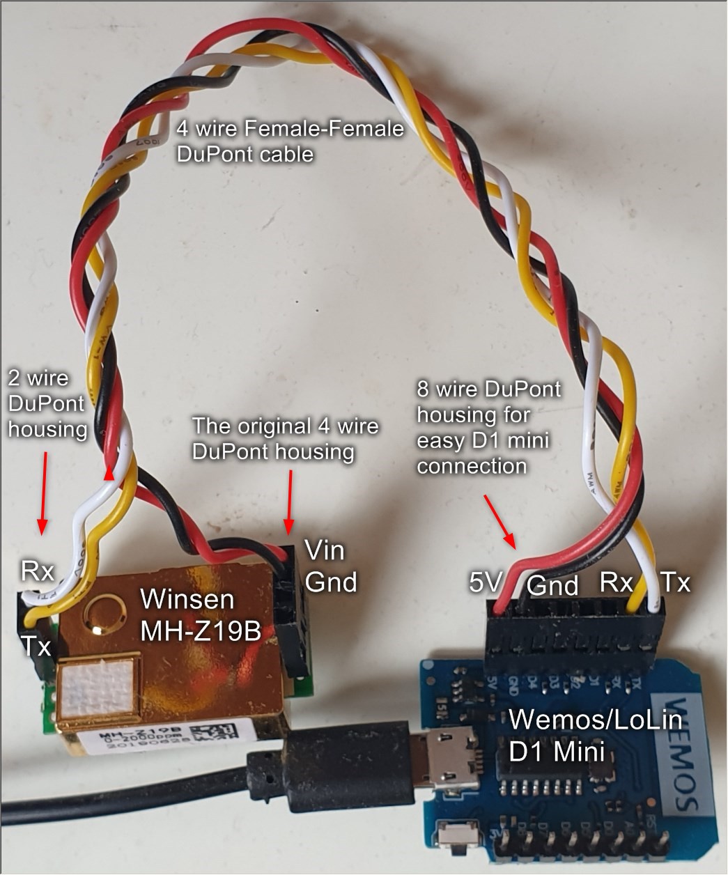
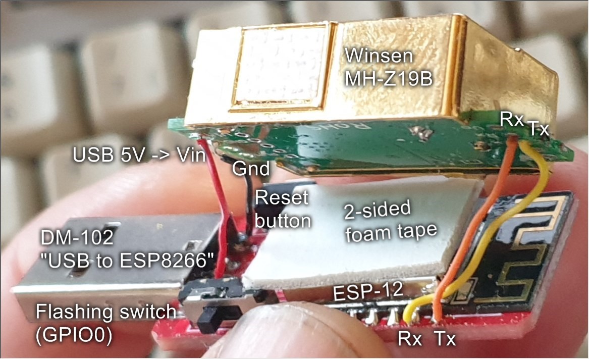
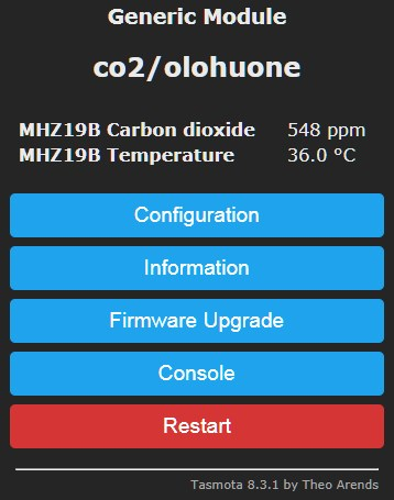
• 1
    Wired Wemos Version

    For the first proto version I chose Wemos D1 Mini, whose I always have by hand. Headers were already soldered, so protoing was trivial. Not the most handsome setup, but can add a case later.

    I picked a four wire DuPont female-female cables (good to have those), replaced two pins from one end to a two pin housing and all four from the other end to a eight wire one to nicely match one row of D1's pins.

    Soldered two dual pin headers to the sensor's GND&Vin and Rx&Tx pins. The MH-Z19B's IO is 3V3, even if it requires 3.6 - 5 Volts for operation.

    Flash first, as the same serial Rx/Tx are used by the sensor. To re-flash by wire (not Over The Air, which Tasmota etc support), detach Rx/Tx from one of the ends.

    Connect accordingly, hardware ready.

    I plan to add a display and print a case for this setup.

  • 2
    Compact DM-102 carrier board Version

    Next I wanted a more compact device, that wouldn't be dangling from an USB cable, so got a "DM-102 USB to ESP8266" board. These boards are excellent for small devices directly pushed to a USB connector, as they have a regulator (of course the power hungry AMS1117 though), USB UART, GPIO zero switch, reset button and the required pull-ups for ESP12-E/F built-in, and price less than $1. These boards are available populated with ESP-12 or 07 modules, but I have mostly the plain boards as they are more versatile, like mounting an ESP32 instead (with 2-3 mm wires for 3V3, Gnd, Tx, Rx, D0, Reset) or rising the module with short wires to be easily replaceable if needed. Now I could have a readily populated module but soldered in an ESP-12S just because those I found first and no need for external antenna (which ESP-07 would support).

    As with the D1 Mini, flash first to avoid serial bus conflicts between the USB UART and sensor. To re-flash with USB, detach "Tx" from the sensor or "Rx" from the ESP (yellow in the photo above).

    When the setup was confirmed working, I taped the sensor on the ESP-12 and tucked wires to safety. To avoid blocking the antenna I mounted one end of the sensor flush with the PCB around the USB connector, so that it wouldn't affect pluggability but have least effect on the antenna.

    In this configuration the ESP obviously heats the sensor, don't know how this affects its accuracy. The sensor also reports temperature, but it has only one degree granularity and doesn't seem too accurate so I'm not collecting it. Internally it likely uses this value to adjust something, but don't know if it should be relative to outside air or the sensor, latter of which would still more or less match if the sensor is heated like this. Better keep the ESP in (deep) sleep as much as possible to avoid this anyway (as well as wasting electricity, the AMS117 has bad efficiency and there can be dozens of ESP devices around a house).

  • 3
    Firmware

    I have several devices flashed with Tasmota, and noticed it supports MH-Z19 out of the box, so that I flashed to the devices using Tasmotizer. Supporting this sensor required the image tasmota-sensors.bin, which can just be selected in Tasmotizer. ESPHome, ESPEasy or ESPurna generally allow more flexibility but didn't have any special needs (for now).

    After flashing SSID setup as usual, with using the ESP's access point or Tasmotizer.

    Selected Module type = Generic (18), GPIO1 (Serial out) = MHZ Tx (60), GPIO3 (Serial In) = MHZ Rx (61), GPIO2 = Led1i (56), and it worked.

    Actually, first selected GPIO1 = MHZ Rx and GPIO3 = MHZ Tx, as that would be logical (TX->RX and RX<-TX) but somehow it works the other way, guess those component names "MHZ Tx" and "MHZ Rx" are mixed. The LED in my ESP-12S was GPIO2, yours might be different, and required Inverted setup (Low = LED on), thus Led1i.

    In addition to module setup, MQTT server was set and the MQTT topic (and device name just for clarity) set to co2/<location> so that I can automatically handle any number in Node-Red, InfluxDB and Grafana.

    CO2 sensors need to be calibrated now and then, the default for MH-Z19B being Automatic Baseline Calibration (ABC) to lowest measured values every now and then (day?), which would be assigned the ballpark outside CO2 figure of 400 ppm. This is far from accurate and cannot be used to monitor rise of CO2 in the atmosphere, but is tolerable for inside air quality measurement, where most rooms will have some hours per day for CO2 to more or less equalize with outside air, and we are mostly interested about rather high concentrations. I'm not totally happy with this approach but prefer not to carry liquid nitrogen canisters around for calibration so letting it be for now.

    To change calibration modes and calibrate, go to Tasmota's Console and use the commands:

    • Disable Automatic Baseline Calibration: sensor15 0
    • Enable ABC: sensor15 1
    • Calibrate in clean outside air: sensor15 2
      • This sets the baseline to 400 (0.04 %), which sure isn't accurate but considered "good enough" for room air quality monitoring.

    There are also commands "sensor15 1000|2000|3000|5000" for setting sensitivity (in particles per million, 1000 would mean 0.1 %). I don't yet understand how does this relate to different sensors, as they are specified with a certain ppm value - would the default be OK, should you set this to match your sensor, or can you change a 2000 ppm sensor to a 5000 ppm one with this?