In the first log of this project, I experimented with IMU sensors as alternative input methods to large buttons and mechanical joysticks. Along with the smart remote prototype we are working on delivering to UCPLA for testing, we want to also deliver an IMU-based input controller as well. In this log, I will discuss the software updates making the joystick more robust and usable for different users.
Previous Iteration
In the first iteration, the code was quickly written to make things barely work enough to demonstrate a concept. For example, raw IMU signals (accelerometer only) was used and threshold values were hardcoded specific to how I wanted to use it. Three improvements are made. First, the raw IMU signals were processed to smooth out the signals to give better results. Second, a calibration routine was programmed and a new thresholding technique was used to detect different position states. Last, a two joystick controller was shown to demonstrate modularity and the ability to expand input capabilities.
The hardware did not changed from the previous iteration. All of the processing is done with a receiving unit, an ESP32 based board. Two M5StickC units ( with an IMU sensor, button, and screen) send signals to the receiver. In this iteration, one M5StickC unit is intended to be worn on a user and the other unit is intended for the caregiver for handling calibration of the system.
Lightweight Signal Processing for Smoothing Data
The IMU in the M5StickC is a 6-DOF IMU, with 3 accelerometer signals and 3 gyroscope signals. With this IMU, all I am trying to do is measure tilt of the unit. The first iteration measured tilt only using accelerometer signals, which is not the most accurate way to measure tilt angles. The problems with measuring tilt from accelerometer signals is any sort of movement including vibration will cause noisy signals.
Tilt angle can also be measured using signals from a gyroscope, with signals measuring the angular velocity. Calculating orientation from gyroscope can be done by integrating the gyroscope signals. The issue with doing the angle drifts from the correct orientation over time.
The most common technique to calculate tilt angles using IMUs is using a Kalman filter to combine accelerometer and gyroscope signals. However, I opted to use a complementary filter which is stupid simple to implement and doesn't need a lot of computation. It combines both methods together to mitigate both noisy signals and IMU drift. Some more detailed info on complementary filters and IMUs in general is found here, which I followed to implement for this system.
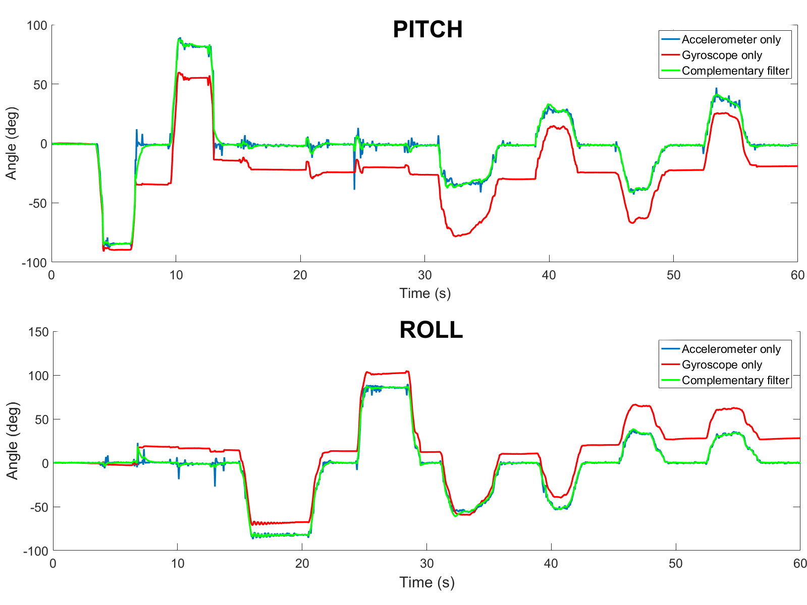
The image above compares the three methods to measure angles based on accelerometer and gyroscope data from one of the IMUs.
Adding a Calibration Routine
The next improvement that was necessary was adding a calibration routine to make this system more robust. Considering that each user with cerebral palsy has different limitations, they won't all be able to use this input device the same way. Thus, a calibration routine is necessary to stay within their motion limits. In my head, the plan that makes sense is to involve a caregiver for setting up the IMU. The IMU will be strapped onto an extremity with decent range of motion. The caregiver will then instruct the user to move in different body positions with each position corresponding to a different button. The caregiver will have a second M5StickC unit, which will give them prompts on a display and a physical button to press to help with calibration. Once calibrated, the information will be written onto the flash memory of the receiving microcontroller to store until the IMU is re-calibrated again.
Once calibrated, the IMU is ready to use immediately. For this initial test (and the first test with users from UCPLA), I wanted to keep it simple and limit the buttons to the four arrow keys on the keyboard. With these hotkeys programmed, I wanted to demonstrate the usability by different users, represented by a quick re-calibration that allowed me to transition the control from my knee to my hand. This is shown in the video below.
This example of playing a game to navigate a car through a maze was chosen specifically to mimic the use of a mechanical joystick to drive a wheelchair. In the future if this system continues to develop, playing a game like this would help benchmark the usability of this system compared to using a mechanical joystick.
With a calibration routine, the method to identify the different body positions changed accordingly. In the first iteration, raw signals were thresholded (if signal>threshold1 -> hit button 1, if signal < threshold 2 -> hit button 2, etc.), which isn't the ideal way especially when trying to scale.
In this iteration, the method was to calculate the root mean square error, comparing between the instantaneous angles (roll, pitch, yaw) and each of the 5 positions(LEFT, RIGHT, UP, DOWN, and NEUTRAL) stored from the calibration. The minimum error from the 5 positions was chosen as the current state.
Adding a Second IMU to Increase "Buttons"
I envision this system being very modular and scalable. If a user only has decent motion in one arm, then maybe they can only use one of these units. However, if a user has motion in both arms (forearms, upper arms, hand) and legs, the possibilities with this system is endless. To demonstrate scalability, a second joystick was introduced.
In this case, I wanted to demonstrate the ability to replace a keyboard to type. One discussion topic for designing the smart remote was how many buttons we should include. With more buttons, the remote gets larger. With fewer button, the user has less control. A keyboard has about 70-100 buttons, so if we had a remote with 100 buttons it would be pretty large.
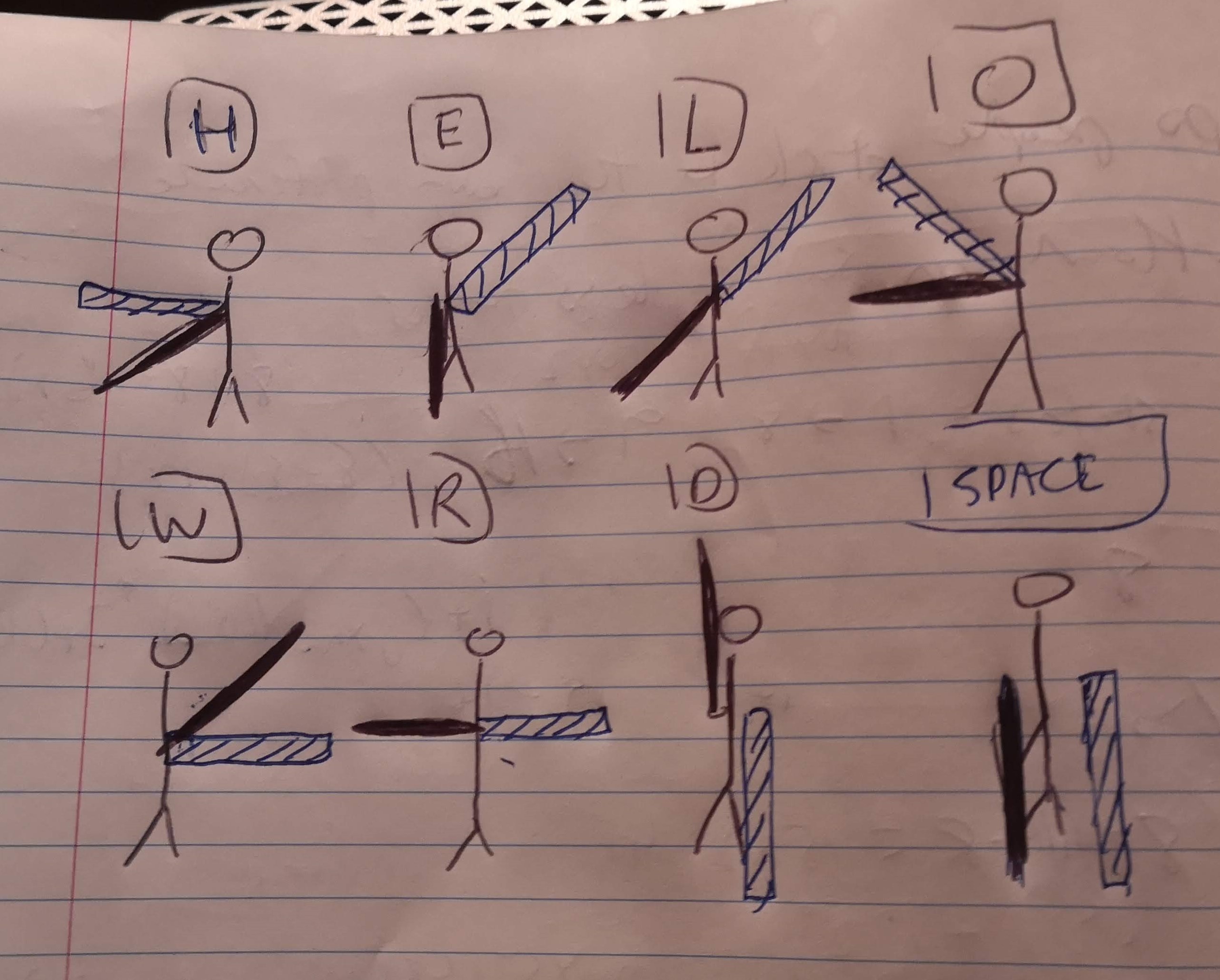
Using two IMUs, I replicated the flag semaphore system to have full capabilities of the English alphabet and more. With this system, arms (and flags) are pointed outward from the body at 45 degree increments of each other. With each IMU, I first calibrated 7 positions, (meaning 14 total positions from 2 IMUs). I didn't show this calibration routine but it is the same as what was shown in the first video, except now both units stream IMU data to the receiver. With two IMUs with 7 position, this gives 7x7=49 unique buttons that can be pressed, more than the 26 needed for the alphabet. For the first test, I used the semaphore system to type "HELLO WORLD", shown in the video below. I might have inverted the positions, so I attached an image of the corresponding system used in the video.
With more positions, it becomes more difficult to map the correct orientation to the right output, so an extra delay was added to ensure less mistakes. With users from UCPLA, this becomes even more of an issue if they have less motor control and is something that needs to be thought about more. Although I think it would be neat to have this system replace a keyboard input device, this might be too much to troubleshoot for the initial test with UCPLA. For the first test that is coming up very soon, work still needs to be done to improve mounting options instead of taping IMUs to the body as well as determine specific testing plans and goals.
Discussions
Become a Hackaday.io Member
Create an account to leave a comment. Already have an account? Log In.
It's cool to see this method being explored further, while keeping in mind the end users!
Are you sure? yes | no