The last couple of weeks were busy preparing for prototype shipment and I kind of forgot to post log updates, so this entry will cover a few topics. While this upcoming week is focused on user testing and receiving feedback on our keyboard and joystick prototypes, this log will focus on the development of an intermediate prototype of a wireless Bluetooth button.
STARTING SIMPLE WITH ONE BUTTON
Currently for this project, we were focusing on delivering two prototypes: the keyboard and the IMU-based joystick. I wanted to add an intermediate milestone to create this wireless button prototype, which could potentially be a third deliverable but more importantly serves as learning lessons for future development of other prototypes. Below, I describe 5 discussion topics regarding this one button.
1) Cost of Existing Big Buttons for Assistive Technology
A lot of buttons and switches that are catered towards use as "assistive technology" are in my opinion, really expensive. A big red button can cost about 65 dollars. A mechanical keyboard switch that we are using for our keyboard input device is more than an order of magnitude less that at $1.06. Going one magnitude further, a tactile switch costs $0.10. From an electrical/hardware perspective, they are all just momentary push button switches. Looking at a previous Hackaday project, the Clunke Button, that project addresses this issue by creating a DIY assistive button using a keyboard switch, an audio cable, and some 3D printed parts.
Now taking a look at wireless Bluetooth "assistive technology" buttons, the cost is also expensive with this model priced at $195. I looked at this button, and challenged myself, could I make a button by only having $19.50 to spend on parts? Below are the list of electronics from Digikey to make a wireless Bluetooth button, with the subtotal coming in at $19.36.
| Quantity | Part # | Description | Unit Price | Extended Price |
|---|---|---|---|---|
| 1 | 1965-1000-ND | ESP32 Board | $10.00 | $10.00 |
| 2 | CH197-ND | Keyboard Switch | $1.06 | $2.12 |
| 4 | SY628-ND | AA Batteries | $0.33 | $1.30 |
| 1 | 36-2478-ND | Battery Holder | $1.79 | $1.79 |
| 1 | EG5619-ND | Rocker Switch | $0.57 | $0.57 |
| 1 | CP1-3513-ND | Stereo Jack | $1.42 | $1.42 |
| 1 | 1175-1491-ND | Stereo Cable | $2.16 | $2.16 |
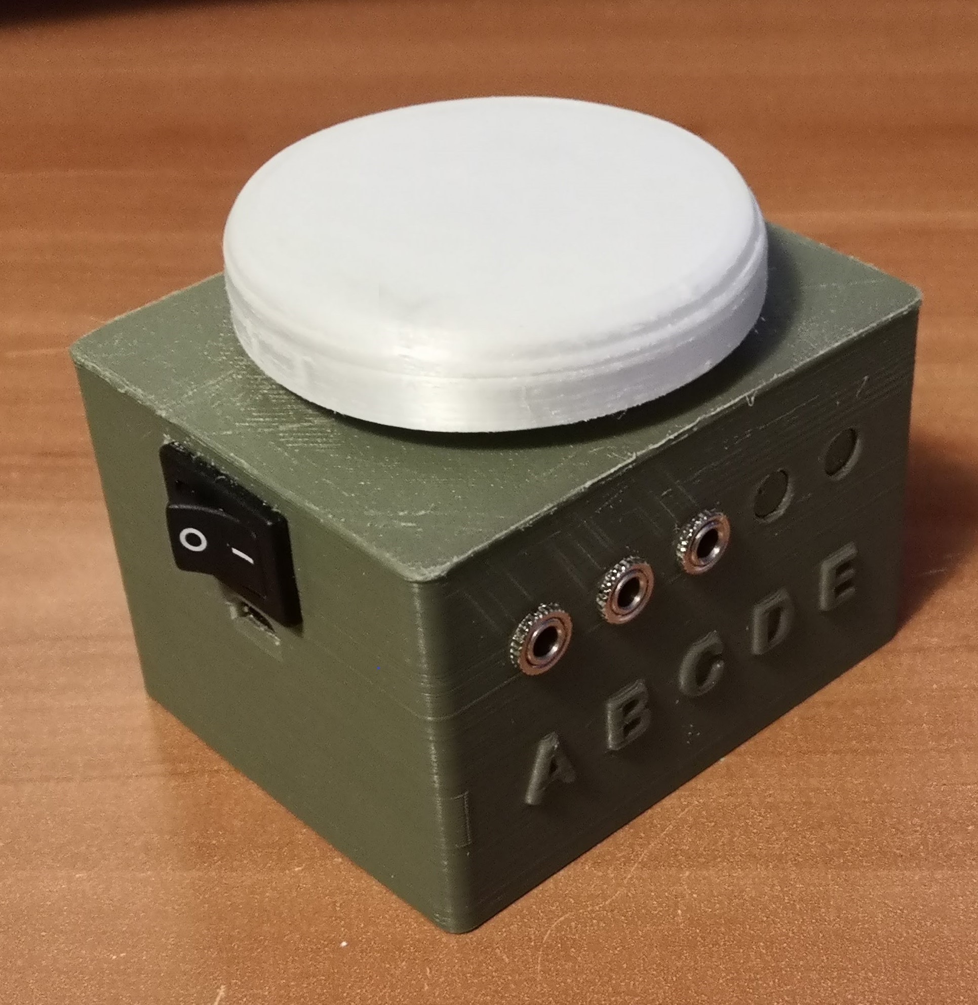
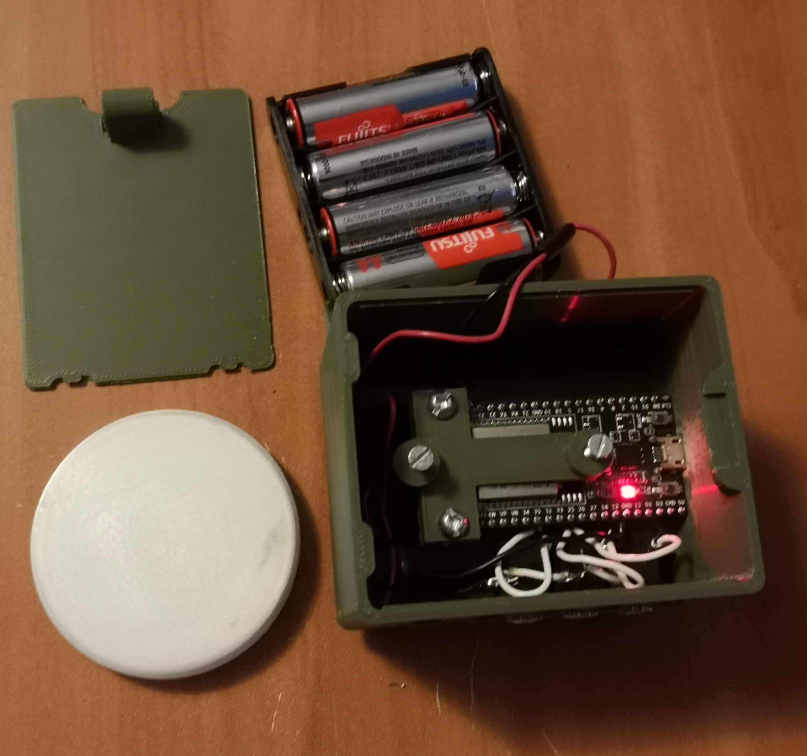
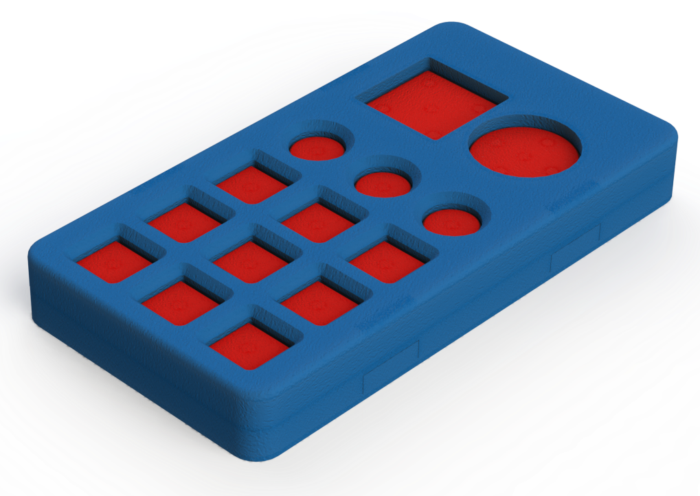
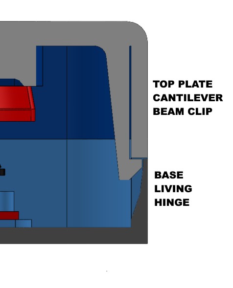
With these parts, 3D printed parts, and some wires and solder, a Bluetooth button with an stereo jack to connect another "Clunke" style DIY button can be made at almost 1/10th of the cost of a commercial alternative, and 1/3rd the price of a just a button. Below is a snapshot of the CAD model with a section cut out and an image of trying to get all the electronics to fit inside the 80x65x52.5 mm housing.
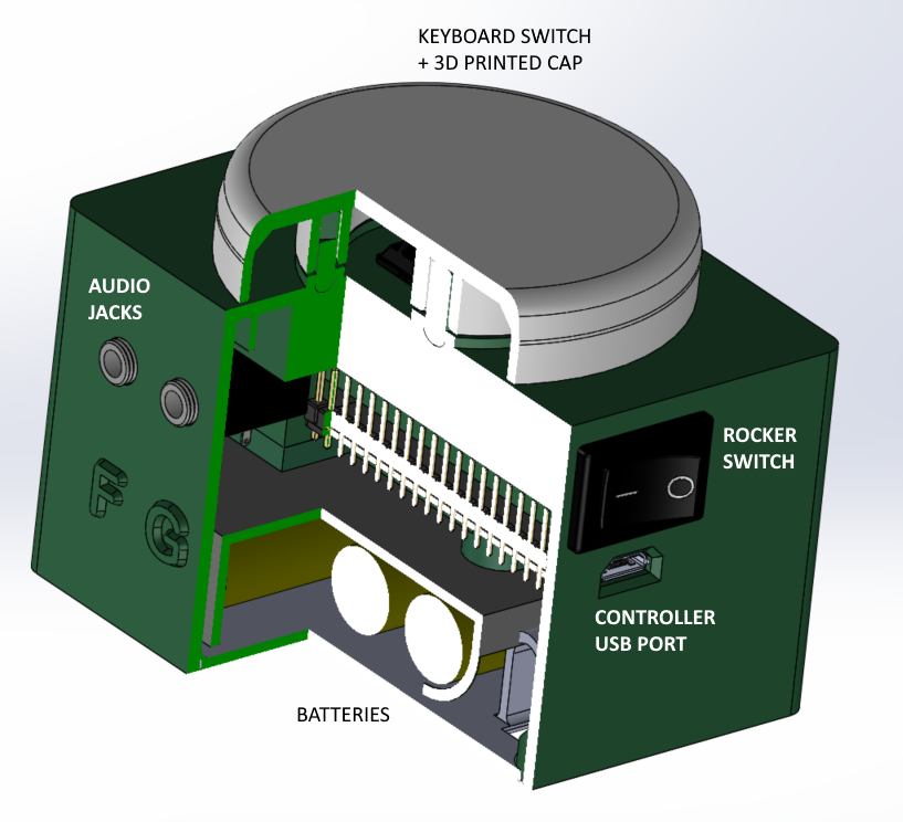
So with $20 worth of electronic components, we can make a $200 button that has Bluetooth connectivity to be used with our platform we're developing. This leads to the next topic, why have just a simple button instead of the other cool devices we're developing?
2) Asking users to deviate from their unique behaviours and tendencies
The keyboard and IMU-based input devices we're developing aren't necessarily commonplace in the assistive technology market. Even if we're designing these devices that we think have added functionality or an improved user experience, it doesn't mean our devices are going to be adopted by potential users. My guess is that there will be a large population that are comfortable using their existing devices and are unwilling to adopt to ours. Thus, it would be helpful to have this iteration that is simple and recognizable to connect their existing input controls to access digital devices through our developing platform. Sometimes, less is more.
3) Maximizing functionality of one button (and then multiplying)
While uploading firmware for this iteration, I was thinking about how to expand the functionality given just one button. There is an Arduino library, OneButton, that helps with this. It can help program a button that distinguishes between a short and long button press, as well as the detection of a double click. With this, one button can now have the capability of 3 buttons.
For users who may have less motor control function, the single click vs double click detection might not be the most suitable as it often requires a delay for a double click. I'm expecting a longer delay between two sequential button presses. I'm not sure it is the best idea to ask someone to press twice quickly given certain individual's motor abilities. Thus, I plan on focus on adding functionality by distinguishing short and long presses, and extending this concept further.
What I hope to integrate is to send pulse vibrations at set time increments (1 -2 seconds or user-defined?) while a button is held down. I think a user would be able to hold down a button, count the number of pulses they feel, and then release it after a certain number of pulses to hit that specific "button". I think this is a way we can extend the use of 1 button to 2 or 3 or 4. Yes, it takes longer to press a button if it takes 5 seconds to hold down. However, if a user was asked to reposition their hand away from their button they are hovering to another button and hit that, that action might also take 5 seconds depending on the user.
4) A Panic Button
In one of our recent meetings, we discussed the possibility of using our platform to keep caregivers and users remotely interconnected. As we are trying to give users more individuality by being able to control digital devices, this will hopefully give their caregivers more confidence to leave the users alone more often for extended periods of time.
With more individuality, hopefully users can be less dependent on their caregivers allowing for more freedom to do other things. If the caregiver and user are physically separated, we can leverage the power of IoT to keep the two interconnected at all times to give both caregivers and users peace of mind. The simplest implementation is to give the user an emergency button, where if the user requires immediate attention, it can press the button to send a text message/email to their caregiver, prompting them to check in. A future implementation that makes more sense is to connect to a camera for remote monitoring. For now, the focus is to get some feedback to see if having an emergency button to send a text message is helpful for different users and caregivers.
5) Button box as a Surrogate for IMU Device for Debugging
Developing this wireless button is helpful for learning lessons to help development of other prototypes, specifically the IMU system. This button box and the IMU joystick share similarities, including the use of the same microcontroller and having 4 buttons. While I experiment with things such as planning a intuitive user workflow and the wireless communication protocol between the platform brain and the input device, I can use this button box to do the debugging. The mistakes and lessons learned can then be applied to to joystick and keyboard prototypes. Also, making this button box was helpful for me because I haven't soldered anything in like a year and was tinkering with a new 3D printer, so I had some rust to shake off before starting the hardware development of the joystick.
JOYSTICK UPDATE
The first prototype that was shipped for testing was an out of the box system, the M5StickC unit. On the hardware side, a lot of upgrades can be made for the next iteration. Three planned upgrades are to increase the battery capacity, including haptic feedback, and integrating a switch to toggle between "states". In addition to these three components, the user testing that will be conducted this week will be instrumental in helping design the packaging and ergonomics consideration of this system. For instance, I am not convinced that all users are comfortable wearing a device for 10 hours a day.
Battery
Within the M5StickC, a small, 85 mAh battery is used to power the device. This device powers the chip (ESP32 Pico), the IMU (MPU6886), and other components (RTC, TFT display, LEDs, etc.). With this small battery running the firmware to stream IMU data to a receiver at a sampling requency of 20 Hz, the device runs out of power in about 10-15 minutes. With a larger battery connected, I played around with the sampling frequency to see how it affcected the device runtime.
| Battery Capacity | Sampling Frequency | Device Runtime |
|---|---|---|
| 85 mAh | 20 Hz | 0 hrs 15 mins |
| 1400 mAh | 20 Hz | 7 hrs 30 mins |
| 1400 mAh | 10 Hz | 8 hrs 45 mins |
| 1400 mAh | 5 Hz | 10 hrs |
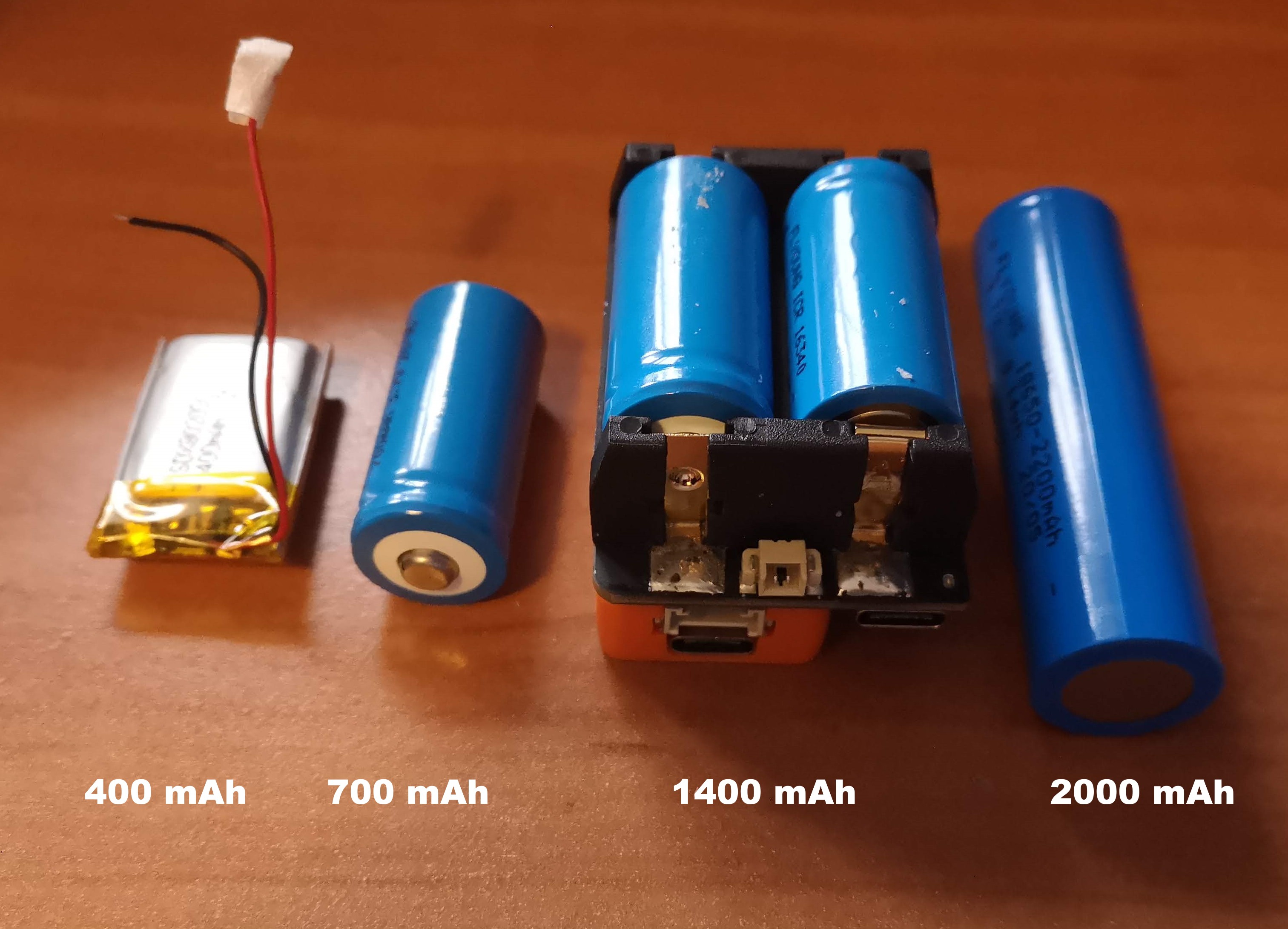
The next battery test I want to do is to replace the M5StickC device with the ESP32 development board and an IMU sensor, to see if the battery is powering unnecessary components. I've already tried to power off as many of the M5StickC components including the TFT display, but I'm guessing there are unnecessary components that are consuming power. My aim is to find the right parameters to get enough runtime of say 5 hours in active usage state. With a larger battery capacity, it also increases the battery size, which would dictate the size of the housing as well. Below are some of the few battery options being considered, while also continuing to search for other options as well.
Switching States from Deep Sleep to Active Mode
A useful functionality of ESP-based boards is the low power consumption during deep sleep modes. Looking online for different tutorials, this implementation seems straight forward for switching states using an external button trigger and is something I plan to play around with in the upcoming days. This button trigger could be something like the one big button device, but I was thinking of using a low profile, non-contact switch. Some ideas include mounting a magnet near the user and connecting a reed switch to the microcontroller, or doing something with proximity sensors. Regardless of the approach of the button trigger, I plan to implement the concept of holding down a button and sending pulses at timed intervals for switching between active modes and deep sleep states.
The figure below is a flowchart/state diagram to switch between device states. It started as a programming flowchart, but then it seemed to make more sense to show it as a state diagram, so its kind of a confusing hybrid.
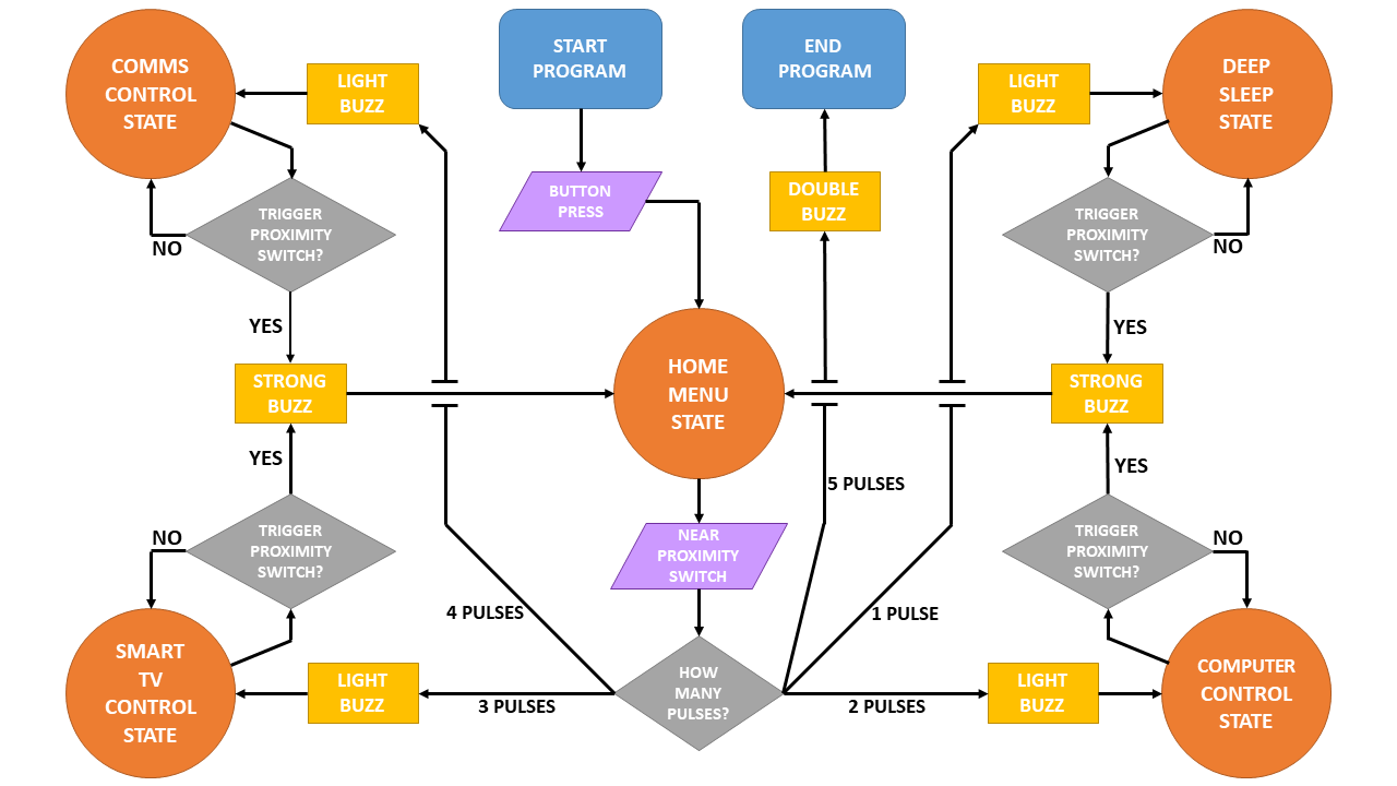
In each state, the joystick is running its own subroutine for controlling the digital device. To switch from one state to another, feedback will be indicated by pulses from a vibration motor. The initial plan is to have a magnet in a fixed location on a wheelchair, where a user hovers the device near this magnet to trigger and toggle states.
This toggling between states is something to be considered for all input devices to switch between peripherals. For the keyboard based input device, the UX becomes easier since there are more buttons available that can be dedicated to state switching.
KEYBOARD UPDATE
The last topic for this update is on the keyboard input device, which was the focus of development a few weeks ago. The current status of this prototype is awaiting feedback from user testing. Potential next steps include moving from a tethered USB connection to a Bluetooth connection, determining the best UI/UX flow, and being able to control a Roku remote with this keyboard. Once this Roku connection is established, we can work on adding this functionality to the IMU-based device as well.
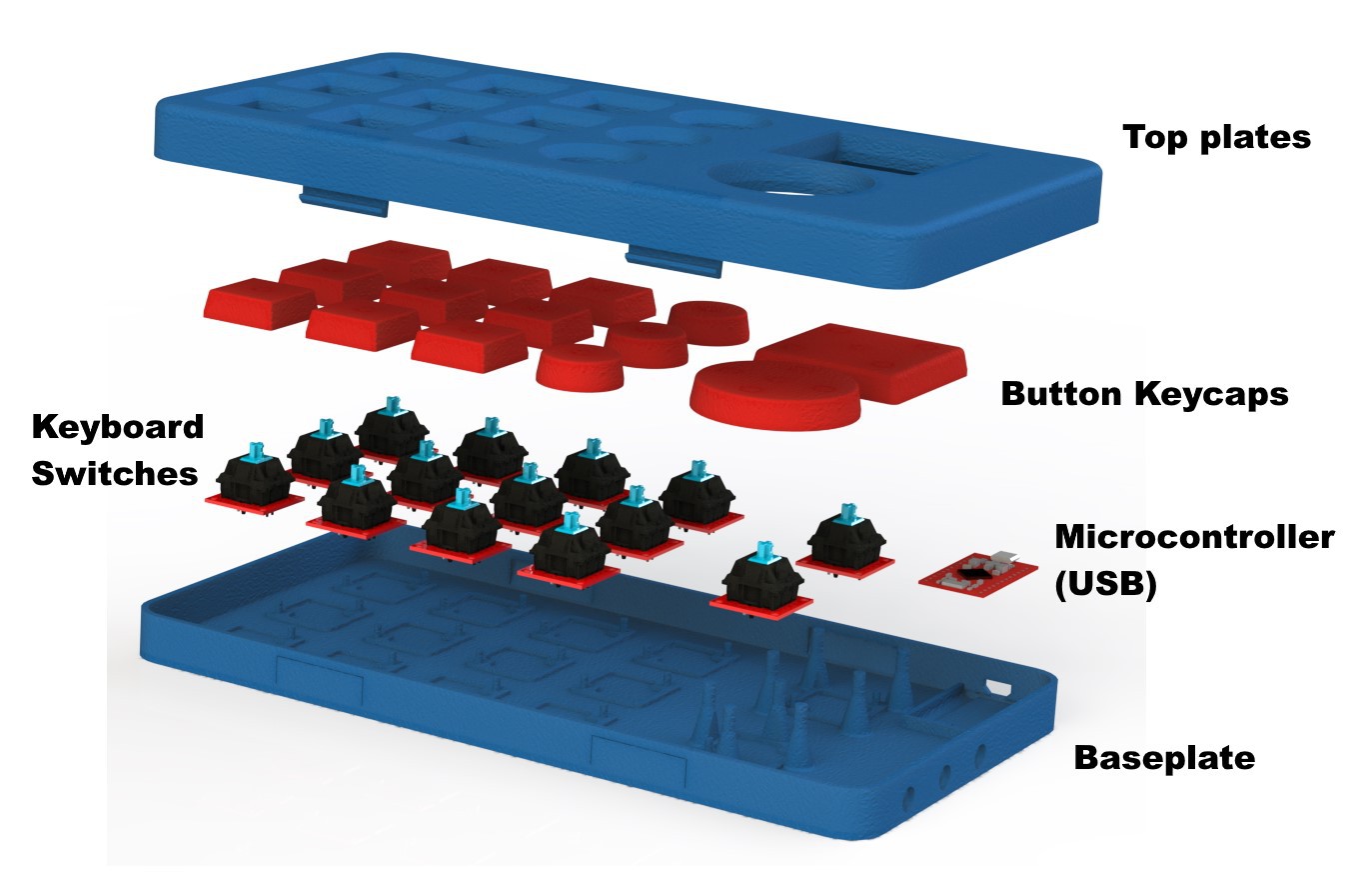
Here are some images from the CAD development of the keyboard from a couple of weeks ago.
Lots left to do and not a lot of time left. Last few weeks will be busy!
Discussions
Become a Hackaday.io Member
Create an account to leave a comment. Already have an account? Log In.