Currently, we've been using the M5StickC platform out of the box as our first iteration of our IMU-based motion sensing remote. At its price point of 10 dollars, it included a lot of components in a small package, great for wearable device development. Below, I summarized a table of the different features of the M5StickC, highlighting the useful components for an IMU remote.
| FEATURE | USEFUL? | NOTES |
|---|---|---|
| ESP32-PICO | YES | low-power microcontroller |
| 6-AXIS IMU (MPU-6886) | YES | main feature of this universal remote |
| Real Time Clock (RTC) module (BM8563) | YES | Important for deep sleep functionality of ESP32 chip |
| Power Management Unit (PMU) (AXP192) | YES | |
| 3 TACTILE SWITCHES | MAYBE | Difficult for the user to press these buttons |
| IR LED | PROBABLY NOT | |
| RED LED | MAYBE | Can be used as an indicator light (i.e. low battery) |
| HEADER PINS | MAYBE | modularity, add more things custom for each user |
| MICROPHONE | NO | |
| LED DISPLAY (0.96") | NO | small display not suited for this population, high power consumption |
| LIPO BATTERY (85 mAh) | YES/NO | Battery capacity needs to be increased to be useful |
The first prototype was helpful in gaining useful insight for our first user testing session. The second iteration will include some additional features to address making the device wireless by having a larger battery, incorporate haptic feedback, and adding a non-contact button for turning the device on/off.
INTEGRATING NEW FEATURES
My initial thought was to use the header pins and attach a second housing to the orignal M5StickC platform, which is seen from some of the hats from their website. With this approach, I tried to imagine what the updated device would look like and could not envision a compact design. I also didn't like the lack of robustness of using the header pins for connecting the additional features.
My next idea was to open up the device and see what the guts looked like. I ended up breaking some parts including the LED display and one of the PCBs. Regardless, there's a picture of the main PCB below.
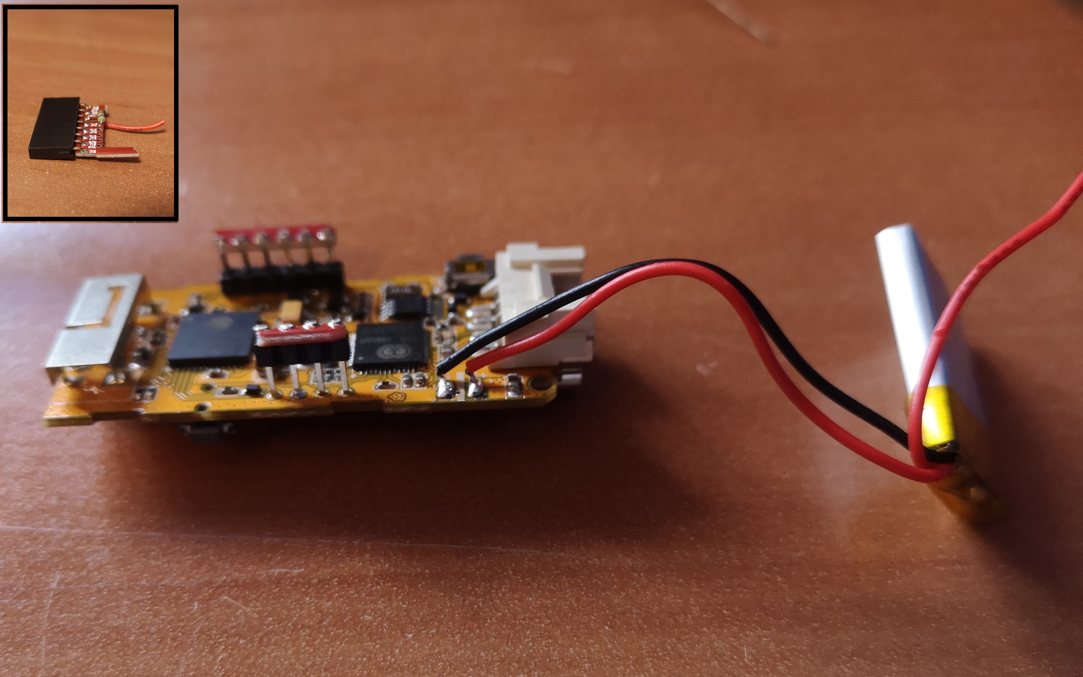
This main PCB had all the main components except including the battery connection and decided to just mount a second board with all my additional features onto the header pins, similar to how the red PCB was attached. This implementation will be shown at the bottom of this log.
LARGER BATTERY FOR PRACTICAL APPLICATIONS
The current 85 mAh battery allowed a runtime of about 20 minutes, not really useful for any applications. Thus, for our first prototype that we shipped out, we instructed our users to keep the device plugged in to a wall/computer.
I measured the current consumption of just sending IMU signals to a receiver to be about 120 mA. I hooked up a 400 mAh battery to the M5StickC and got just over 3 hours of runtime, which correlated to the current measurement. When I set the device to deep sleep mode, it drew about 10 mA, which is higher than the 10 uA of current draw in deep sleep mode of the ESP32 development board. This is something I still need to look into. I also measured the current while the device was turned off and was surprised to find it drew about 7 mA of current. After looking at some online forums, it seems like this wasn't a mistake and is a bug of the platform. For this application where I'm not requiring a device to run for months or years, I think the current consumption at off/deep sleep states are good enough for now.
I ended up choosing a 1,000 mAh battery which would extrapolate to about 8 hours of runtime of just sending IMU signals. However, considering I want to power a vibration motor and maybe other features, the runtime would probably reduce by an hour or two. This battery has dimensions of 50 x 32 x 5 mm and weighs 24 grams. It is both the largest and heaviest of the electronic components, which will strongly influence the housing size.
VIBRATING MOTOR FOR HAPTIC FEEDBACK
For users who have difficulty with line of sight, having a solution that solely relies on visual feedback isn't ideal. Many of these users can sense touch, so it makes sense to include some vibrations similar to our phones. I tested two different vibrating motors and didn't really feel a difference in vibrations or see a significant different in current consumption or size. Currently, I am planning to use this one. There are still unanswered questions regarding UX, such as when to send pulses and the types of pulses (two short pulses, one long, etc.) that makes the most sense in different scenarios.
REED SWITCH FOR STATE SWITCHING
The current method for changing states from on and off is by using a small tactile switch on the side of the M5StickC device. It is way too small for a user with cerebral palsy to use this switch as even I have difficulties pressing this button. This functionality of switching from active state to sleep state is critical for extending battery life and device runtime and needs to be able to be done by the user.
The easiest option is to integrate a large button, such as the one from our keyboard input device or the one button device. This option is not being ruled out, and I would consider it the fallback option. An alternative would be to use the tactile switches on the PCB and make a larger button that's easier to press. However, this would increase the size of wearable device and makes the design more clunky.
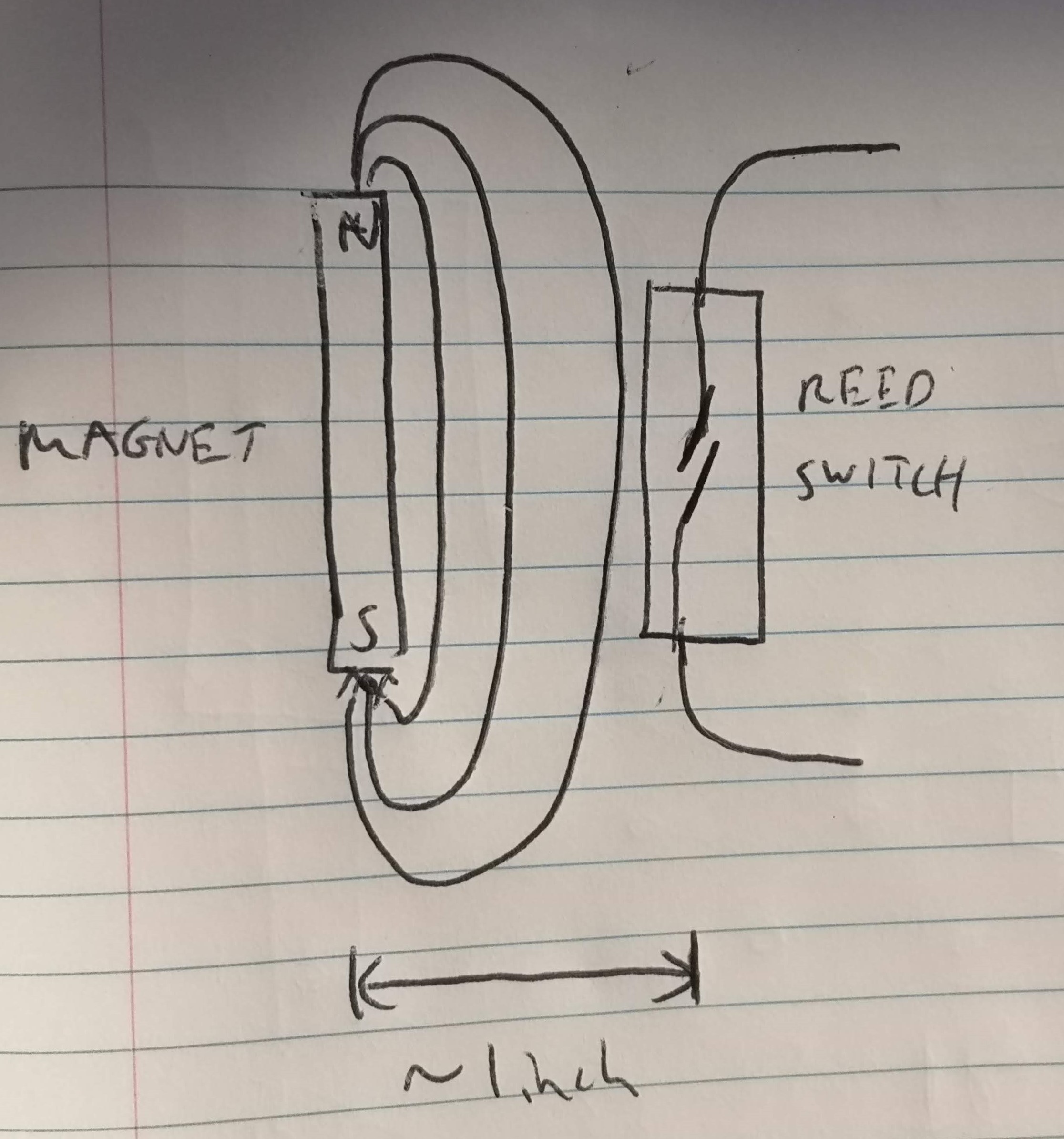
The direction I'm leaning towards is to have a reed switch attached to the IMU device, which gets activated near a magnet. From initial testing with a weaker rod rare-earth magnet, I was pretty satisfied with the activation range with the weaker magnet, and could turn the switch on from about 1 inch away. The ideal alignment of the reed switch and magnet is shown in the picture below, but even if it wasn't perfectly aligned, it still worked at a certain distance.
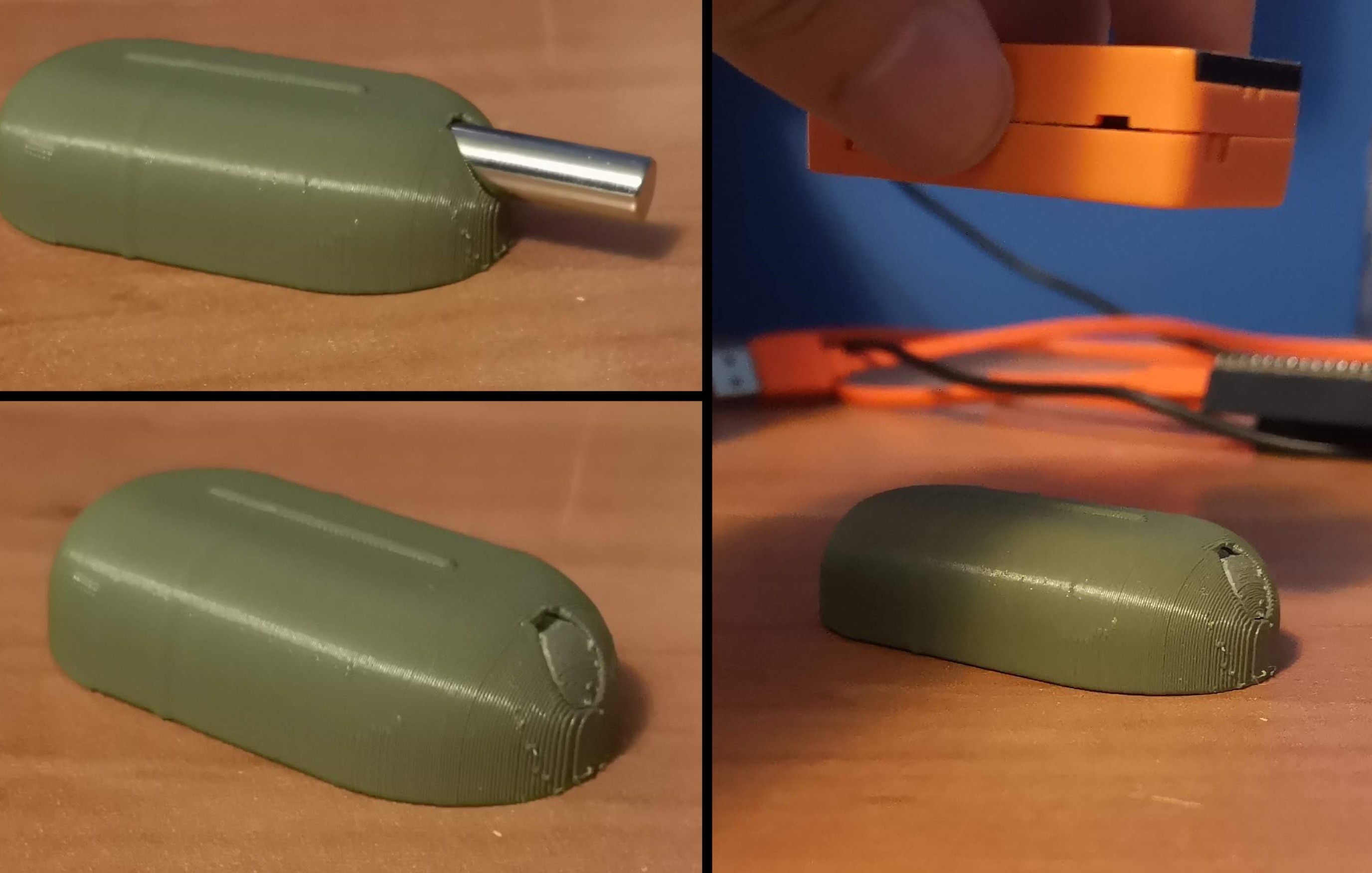
I bought a larger, stronger magnet and wanted to test the increased range, but ended up breaking the reed switch before I could :'(. The plan is to encase the magnet inside a housing (there's a safety issue with using strong magnets so having some separation distance can be beneficial here) that can be mounted to a wheelchair or desk near the user at all times. Another test to find the activation range of the switch will be done before finalizing the device. Below are images of the first prototype of the magnet housing.
PUTTING IT ALL TOGETHER
For integrating the battery, I snipped off the two wires connecting the existing 85 mAh battery and replaced it with a larger 400 mAh battery, which is a substitute for the 1000 mAh battery for the final iteration. I didn't see any issues with doing this and was able to charge the 400 mAh battery through the USB-C port. Initially, I was going to use an external battery charger board, which would have been an extra component for this device. By replacing the battery in this fashion, I can utilize the on-chip LDO voltage regulator and save some space. The other change was to increase the charging current, proportional to the increase in battery capacity. I intend for the final charge current to be about 500 mA, meaning it will take 2 hours for a full battery charge for a 1000 mAh battery.
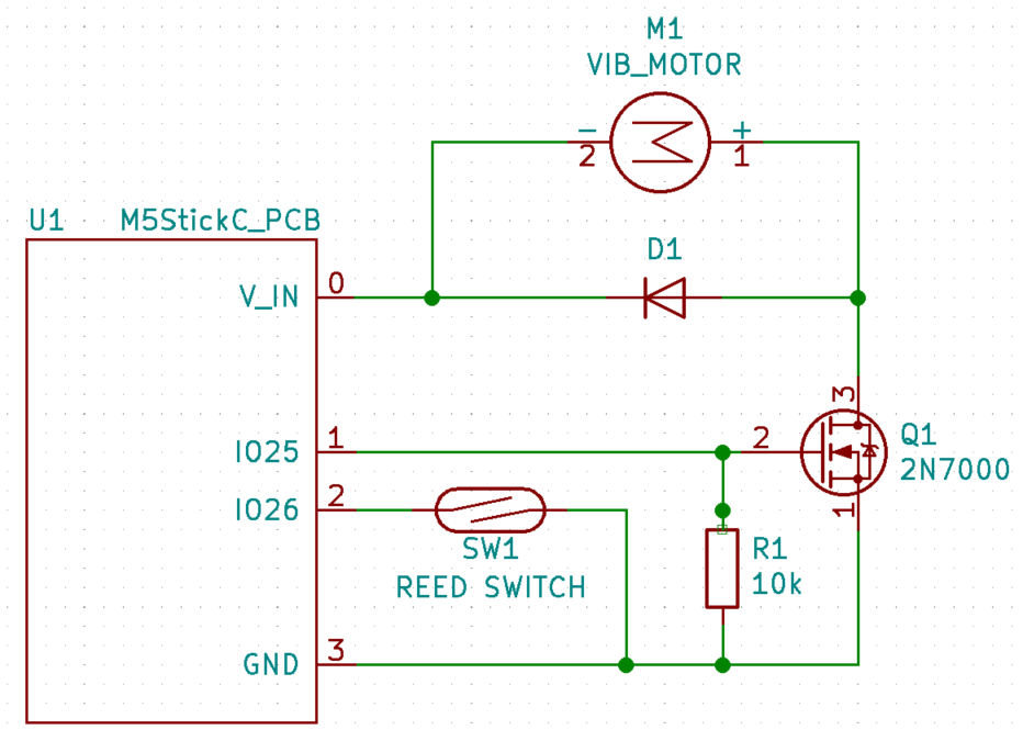
For integrating the vibrating motor and reed switch, I snipped part of a Protoboard and soldered it to some of the header pins, mainly the two GPIO pins that I could identify on the existing PCB. The additional parts were soldered onto this board to make the motor and switch function. Since I broke the reed switch, I replaced it with a limit switch for now. I also only had this one large transistor, which can be replaced with a smaller one. With adding these components in this way, I don't envision the housing size to be increased significantly by the reed switch/vibrating motor integration. The images below show the board itself as well as a schematic of the additional components.
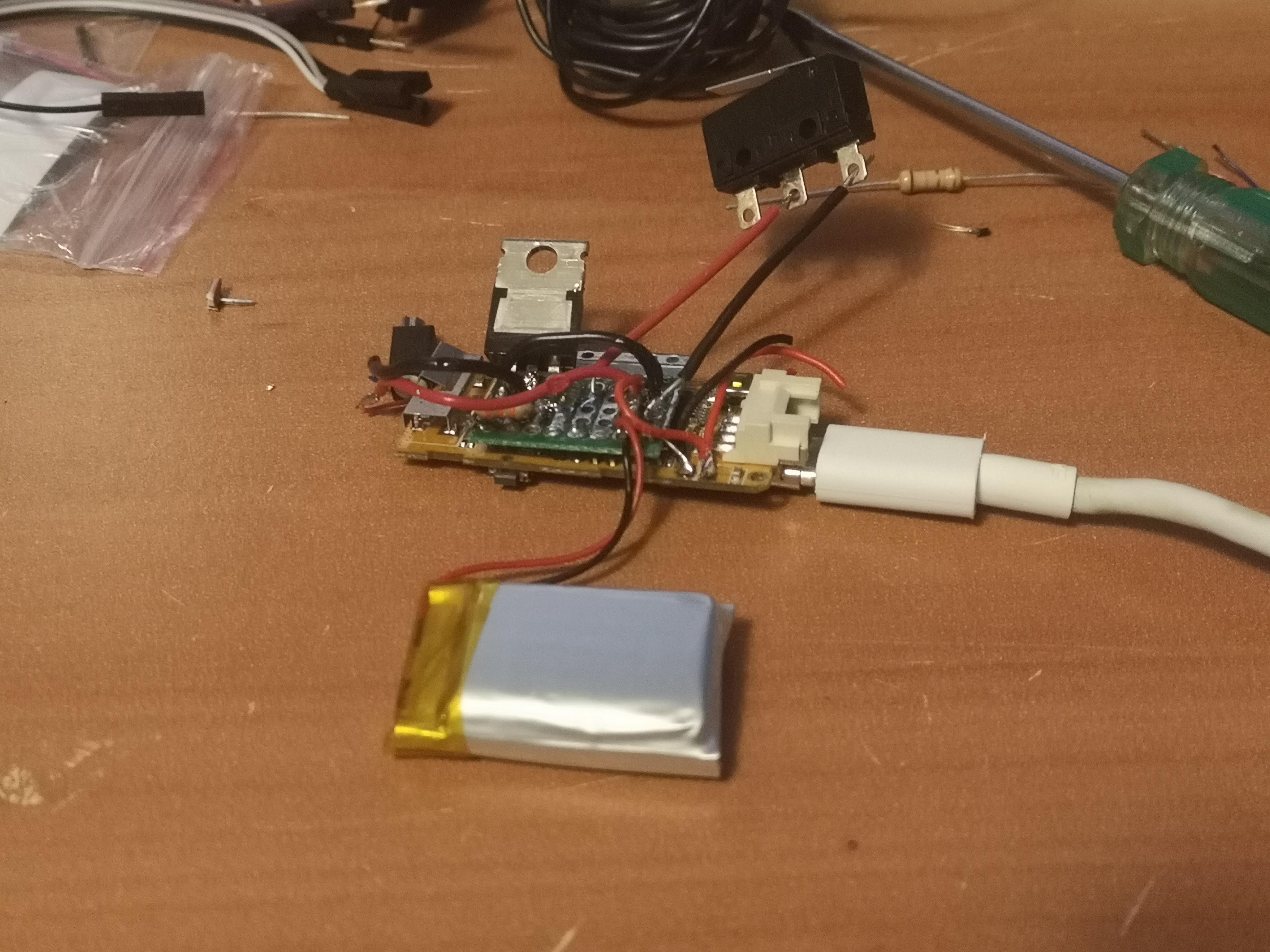
The device shown above is functional (motor vibrates, limit switch works, battery charges/discharges and doesn't explode, IMU signals send to a receiver). I'm not sure how much time there is left in this project to replace the Protoboard with a PCB. The next task, which is of higher priority, is to work on the packaging of the wearable IMU device.
Discussions
Become a Hackaday.io Member
Create an account to leave a comment. Already have an account? Log In.