 alexwhittemore
A key feature of the LIDAR Compass concept is a visible laser firing out in the same plane as the sensor to indicate where measurements were taken that fall in-spec of the design. A key enabling factor of such a scheme is that the LIDAR already has a rotating scan head that we can easily piggy-back on for aiming the feedback laser. This does require, however, that we KNOW the precise position of the rotor head at all times, so we can know whether to enable or disable the feedback laser.
Sensing Rotational Position
There are a couple ways to do this:
- Hall effect sensor
- Magnetometer
- Optical tachometer
In the case of the hall effect sensor scheme, a magnet on the edge of the rotor passes by a hall effect sensor, which measures magnetic force. Whenever the magnet passes, the sensor outputs a pulse, which is read by a microcontroller. The period between pulses gives the average rotational speed over the last full rotation. After timing out a few such rotations, the microcontroller can infer the rotor's position at any time by calculating the solution to (angular position/360)=(time since last pulse/average period). Sensored brushless DC motors use a scheme like this, with a hall sensor at every pole to tell the motor controller when to commutate.
The magnetometer measurement similarly uses a magnet, but instead of a normal axially-magnetized magnet that pulses a sensor when it goes by, you place a diametrically-magnetized magnet right over the axis of rotation, and put an electronic compass right over that. This is a bit like rotating a bar magnet above a compass: the compass always points in the exact direction the bar magnet is facing at any given time, allowing you to read the rotor position directly. This is a relatively expensive way to do things, and requires having access to place a sensor right along the axis of rotation, so it's relatively uncommon. However, I wouldn't be too surprised if this is how the RPLIDAR A1 itself operates, given the need to know angular displacement precisely.
The optical tachometer scheme is spiritually exactly the same as the hall sensor scheme, but instead of using a magnet and a magnetic field sensor, you use a reflector and a light sensor. The biggest advantage of this scheme is that you don't have to put a heavy magnet on the precisely-balanced LIDAR rotor; a dot of paint will do.
Implementing the Optical Tachometer
Advantageously, a sensor that looks a LOT like this is pretty common in DIY robots. Since infrared LEDs and photodiodes are both quite cheap, cheap toy robots very often use simple reflectance sensors based on these parts for obstacle detection. An LED lights up the scene, and if the photodiode sees enough reflected infrared light, the sensor triggers, assuming a nearby object is reflecting that light.
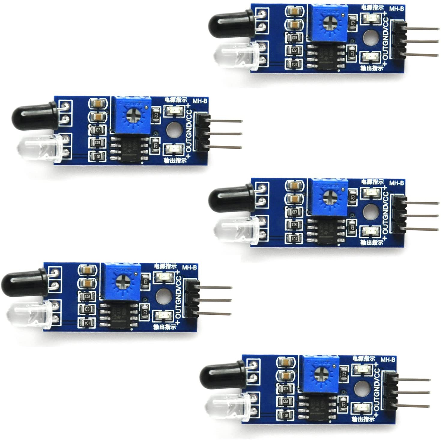
The sensor pictured above, $9 on Amazon for 5, includes a dual op amp and a trim pot to let you set the sensitivity, and to threshold the measurement into a digital "obstacle/no obstacle" output. That happens to be almost everything we need to make an optical tachometer: the only additional item we need is a "snoot" or shroud to direct the infrared light at our paint dot on the rotor, and make sure the receiver photodiode ONLY sees light reflected from that dot. A simple job for a 3D printer:
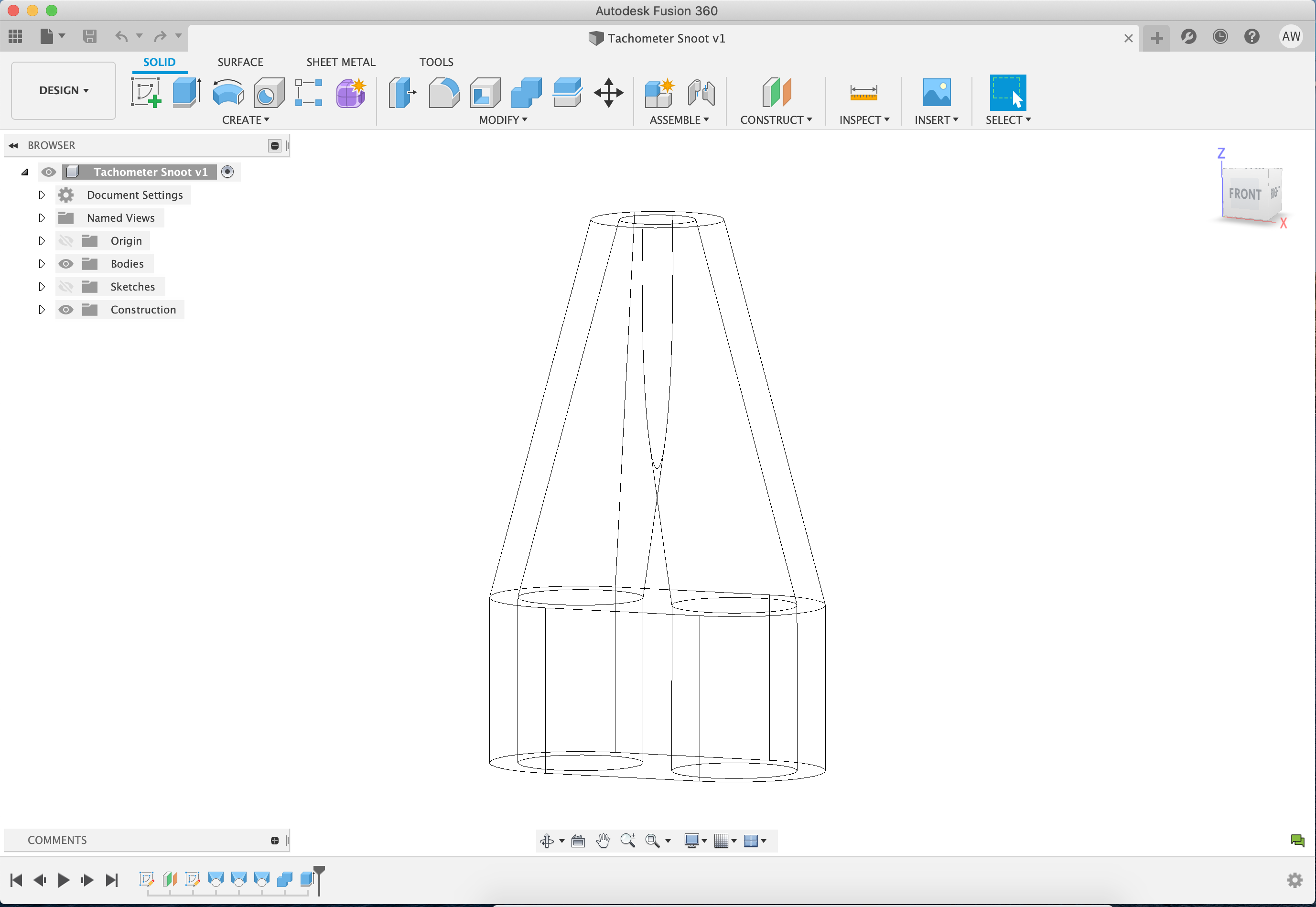
This feels almost too easy at this point, but it's worth pointing out here one gotcha of this idea: plastics are very often transparent or near-transparent to infrared, especially acrylates, even when colored. It's very possible that this snoot doesn't work well enough to block other sources of reflectivity without an additional coat of paint or something. But let's go ahead and try it anyway (printed in black PETG). We'll be looking to measure the white paint dot on the rotor below. Note that it isn't really critical WHERE the dot is placed, as long as it's not the same plane as the measurement laser so our sensor for it won't block the measurement. We'll have to calibrate this after the fact anyway, since it's unlikely the edge of the sensor pulse precisely lines up with any exact geometry of the dot. More likely, some "amount" of dot comes into view before the sensor reads high enough to trigger a pulse, and getting that alignment repeatable between units with a trim pot probably won't ever happen anyway.
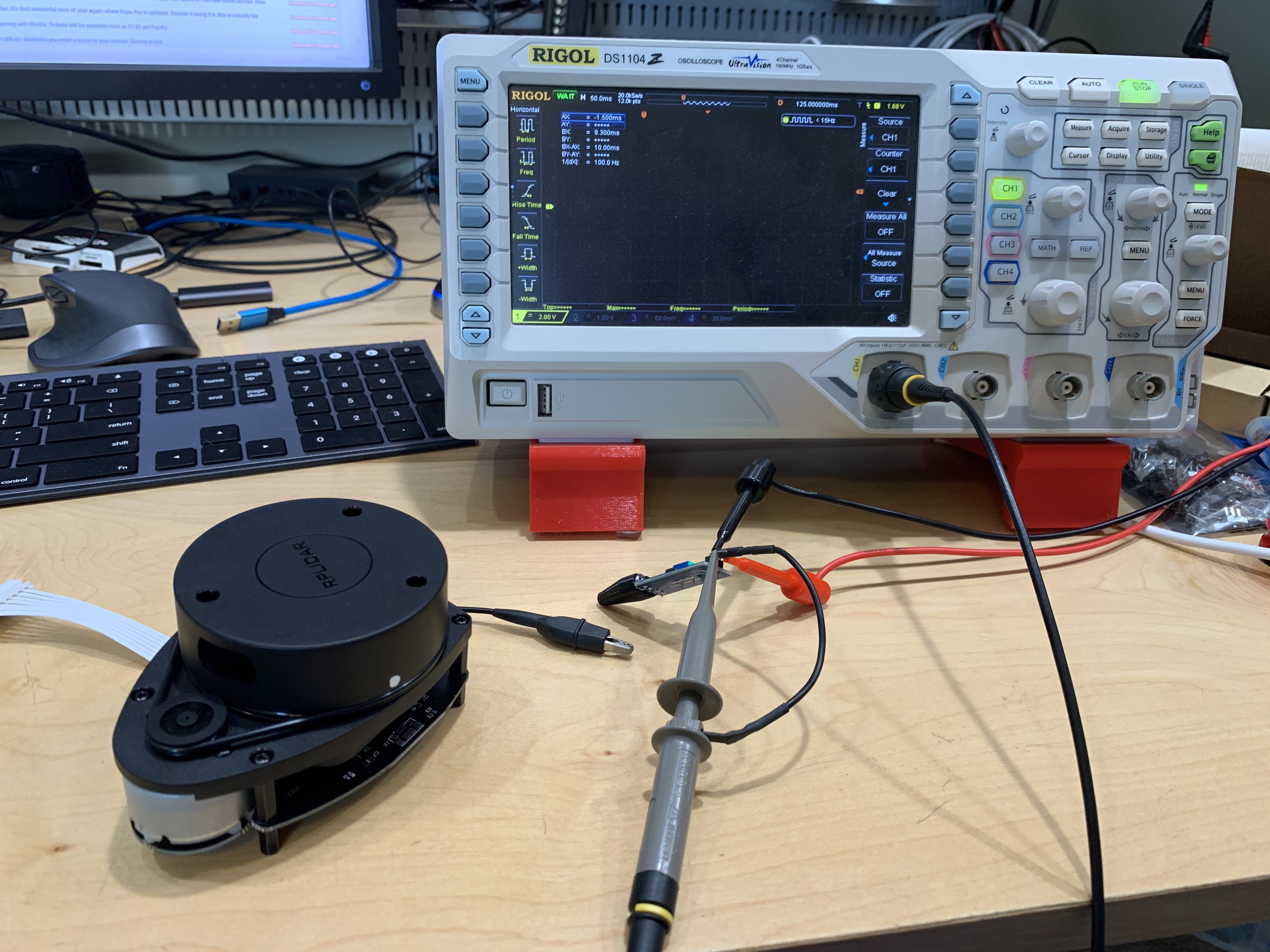
As it happens it WAS Just this easy: the snoot works great, the sensor only reacts to reflective objects directly in front of it, and the dot does a perfect job creating a high contrast between rotor (off) and dot (on):
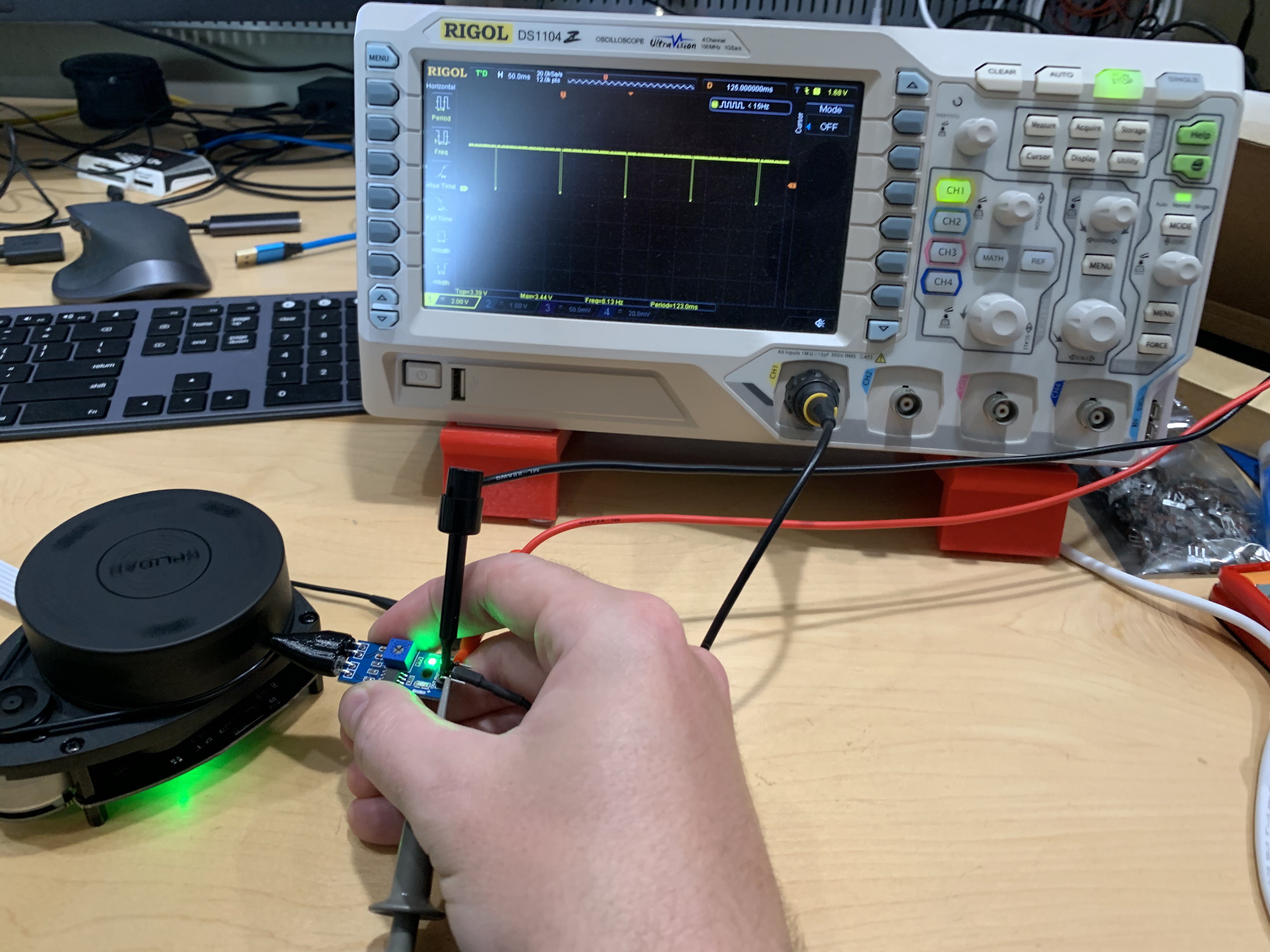
Using basic measurements on the scope, I was able to determine a period between pulses of 123ms, for a rotational frequency of about 8.13Hz, given a motor voltage of 5V as the unit comes stock powered by USB. And of course, if I put a finger on the rotor to slow it down, we can see that too.
So it looks like the physical housing to hold this sensor in the right spot is going to take a lot more design effort than the sensor itself, which is exactly what we like to hear!
Discussions
Become a Hackaday.io Member
Create an account to leave a comment. Already have an account? Log In.