 Leonardo Ward
In this log I'll present 2 design examples, in each case I'll evaluate simple equations in the field of Fluid Statics to answer common questions and verify how each design performs under specific circumstances.
Theory
To start the analysis I'll briefly present a brief explanation of the equations and concepts that will be used in the following design examples.
Archimedes' Principle: any body completely or partially submerged in a fluid (gas or liquid) at rest is acted upon by an upward, or buoyant, force, the magnitude of which is equal to the weight of the fluid displaced by the body.
Where
Since we are designing devices that will work on seawater at different depths, I'll be using following table with density changes depending on depth (seawater 35 parts per thousand and 0 °C):
| Depth (m) | Pressure (decibars) | Density (kg/m^3) |
| 0 | 0 | 1028.13 |
| 1000 | 1000 | 1032.85 |
| 2000 | 2000 | 1037.47 |
| 4000 | 4000 | 1046.40 |
| 6000 | 6000 | 1054.95 |
| 8000 | 8000 | 1063.15 |
| 10000 | 10000 | 1071.04 |
For our design we need to consider 2 specific situations:
- The object is floating at the surface
The sum of all forces that act upon the object must be higher than zero to assure that it floats to the surface, in that situation there is a force in the positive vertical axis that affects the object. When the object arrives to the surface the acceleration descends to zero. To assure that the object floats at surface level:
It is common to add a safety factor to the mass in the equation [1], a small fraction of the mass is added to consider small differences between the design and the real platform or measurement errors. This factor is usually picked between 1% and 5%.
In this equation m represents the total mass of the object, that is the sum of the submerged platform or structure and the buoyancy material.
- The object dives until it reaches the desired depth
Opposed to the last example, the sum of forces that act upon the object must be lower than zero to assure that it sinks, in that situation there is a force in the negative vertical axis that affects the object. When it reaches the bottom of the ocean it stops moving in the vertical axis, to assure that the object stays at the desired depth:
In this equation m represents the total mass of the object, that is the sum of the submerged platform or structure and the buoyancy material.
Similar to the last example, it is recommended to add a safety factor to the mass of the object (can be between 1% and 5%) [1] :
If the design requires additional ballast, it is possible to add it to the equation:
![]() Design Example 1
Design Example 1
For this example I used catalogs to find real buoys and ropes. First I found a buoy catalog:
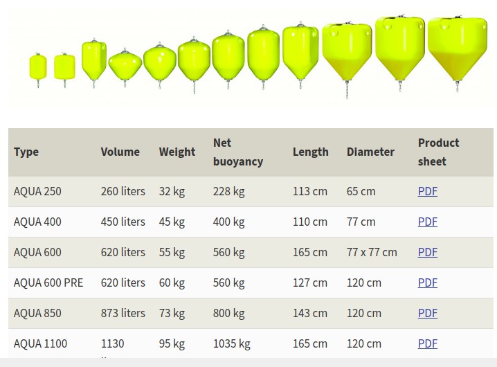
Net Buoyancy
With the available data is very easy to verify the calculations used to determine the Net buoyancy in this catalog. For example for the model AQUA 250:
The fluid considered in the catalog is water. In further calculations I'll use the density of seawater, and I'll adjust depending on the depth.
Ballast
How much weight should a ballast have to sink the buoy to a 500 m depth?
With a seawater density of 1032.85 kg/m^3 and a safety factor of 5% we can calculate the mass of the ballast:
How can we interpret this result? Can we just find something with a 234.941 kg weight and use it as a ballast?
Is not as easy as that, it is important to remember that any object used as a ballast will occupy a volume under water. The ballast will also be subject to a buoyancy force.
For example, we can use a commercial solution for the ballast: a stainless steel ballast weight.
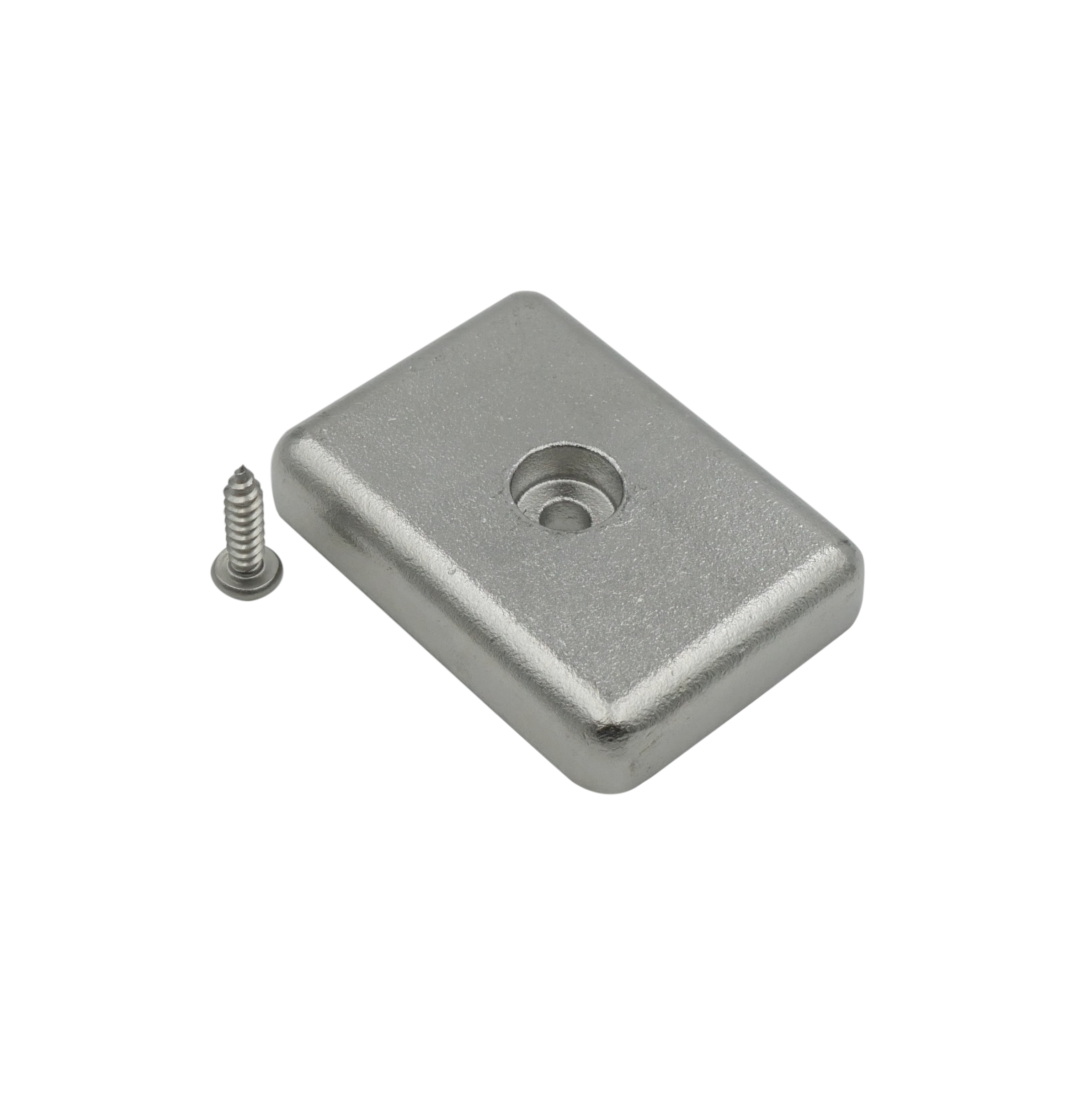
The manufacturer of the ballast provides the weight in air (191 g) and a weight in water (165 g). Having the weight in water facilitates the calculations, to sink the buoy in our design we would require 1424 ballasts.
It is recommended to verify how the manufacturer calculates the "weight in water", to be sure of the characteristics of the fluid. Using the volume and the weight of the alternative used is enough to calculate the net buoyancy of the ballast and then calculate the "weight in water".
Rope and Ballast
Our design requires a rope that connects the buoy and the fishing trap. To add that element to the design I selected a commercial rope (as example) that is used to pull crabs and lobsters traps.
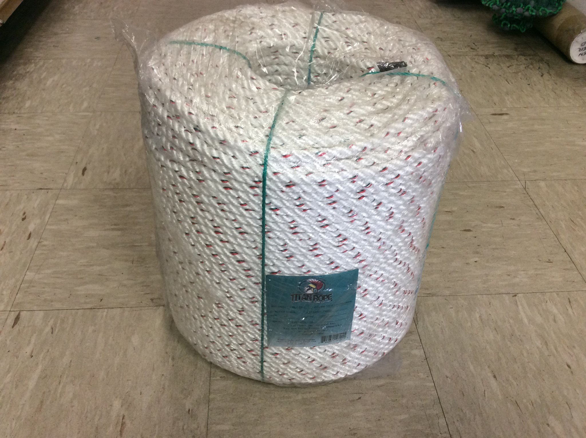
The characteristics of this pack are:
Length = 1200 ft = 365.76 m
Total Weight = 50 lbs = 22.67 kg
For this example I will analyse 500 meters of rope, the total weight for that length is 30.99 Kg. For a ropeless gear situation we can analyse 2 situations:
- The buoy is at the bottom of the ocean, attached to the rope and the trap. Considering our buoy and our rope, the require ballast mass is:
- The buoy is at the surface, attached to the rope. In this case it is possible to calculate the fraction of buoy's volume that stays submerged.
Design Example 2
For this example I used a 32 oz Nalgene Bottle as the buoy. The bottle has a volume of 0.94635 litres and a weight of 0.1772 kg.
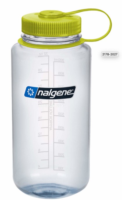
Net Buoyancy
The net buoyancy of the bottle (close to the surface) is:
Ballast
How much weight should a ballast have to sink the buoy to a 500 m depth?
With a seawater density of 1032.85 kg/m^3 and a safety factor of 5% we can calculate the mass of the ballast:
Using the the stainless steel ballast weight from the last design example, it is possible to calculate how many of them are required to sink the buoy in this design.
If we decide to use that commercial model, we would require 5 of them to sink the buoy.
Rope and Ballast
Using the same rope from the last design example I can calculate the maximum length of rope that can be attached to the buoy without sinking it.
Considering the characteristics of the rope used in the last example: Length = 365.76 m and Total Weight = 22.67 kg.
References
[1] J. Cappelletto, M. Massot-Campos, A. Bodenmann, S. K. Das and B. Thornton, "Micro-Ballast Dispenser for Long Endurance Underwater Mapping Platforms," 2019 IEEE Underwater Technology (UT), Kaohsiung, Taiwan, 2019, pp. 1-8, doi: 10.1109/UT.2019.8734317.
Discussions
Become a Hackaday.io Member
Create an account to leave a comment. Already have an account? Log In.