 Leonardo Ward
Similar to the development board that we designed to test the RFM95W (LoRa), we designed a new PCB for the ANTENOVA M20050-1 and the ATGM332D-5N31. Those are 2 promising GPS modules that we are considering to replace the module that we used in our previous design, the Adafruit Ultimate GPS.
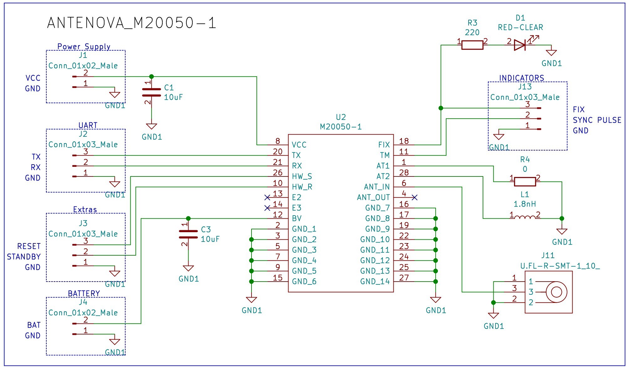
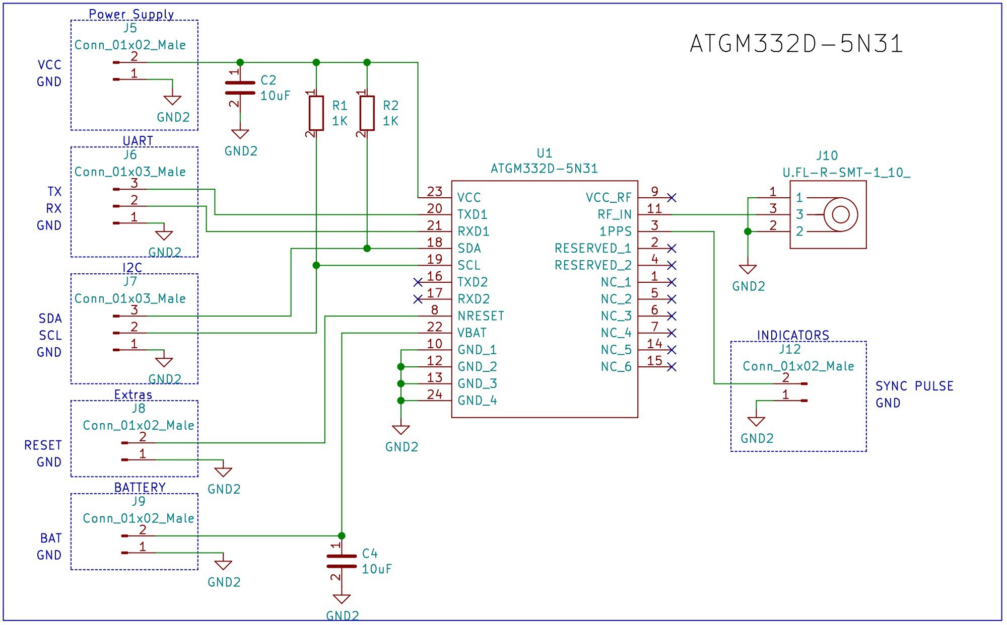
The schematic is very simple, for each module we included a few decoupling capacitors, a U.FL connector for an external antenna and some headers to have access to different peripherals.
The design can be found in the following Github repository.
Schematic for the ANTENOVA M20050-1
Schematic for the ATGM332D-5N31
Also, we are going to test a couple of battery holders.

Bill of Materials
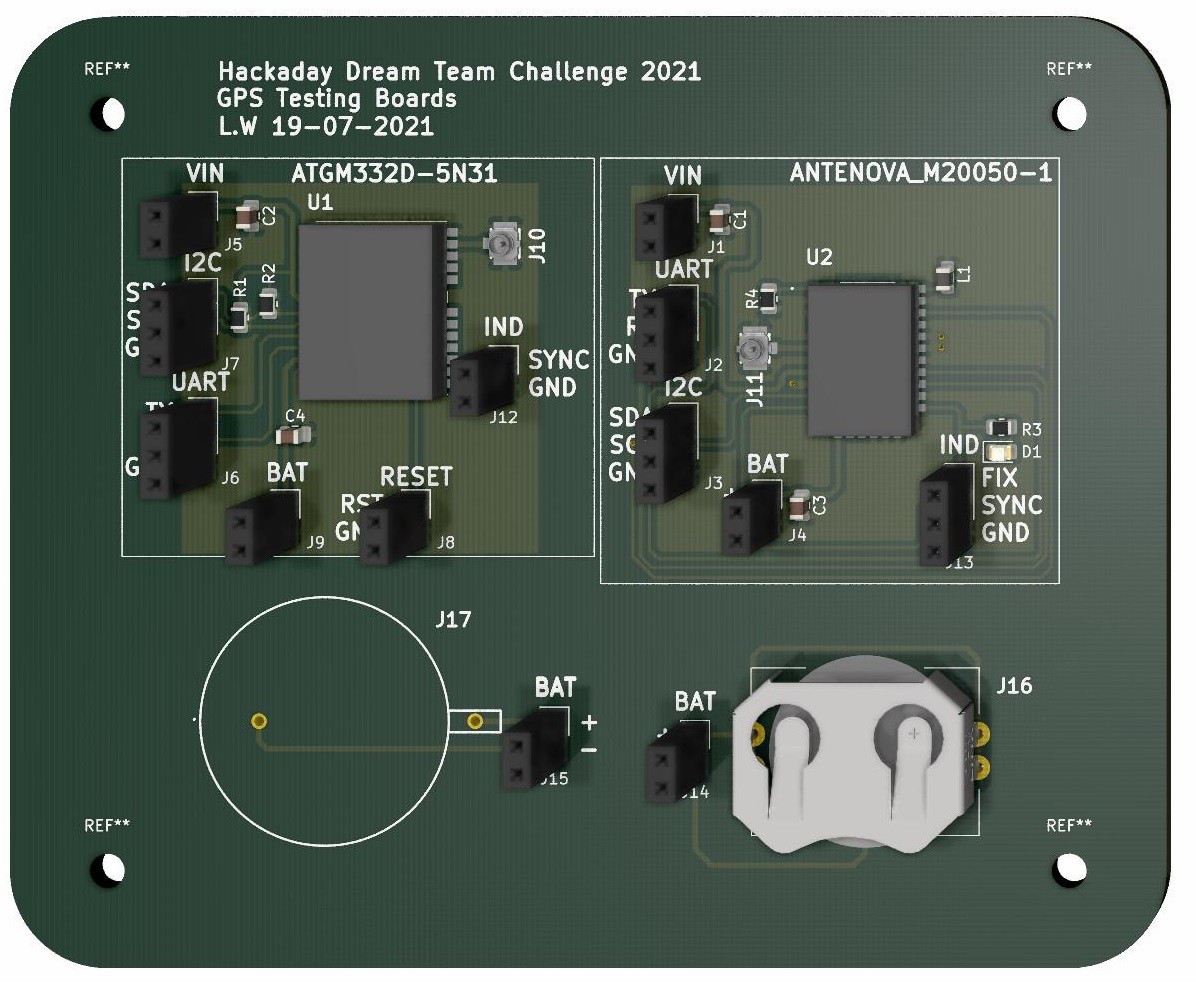
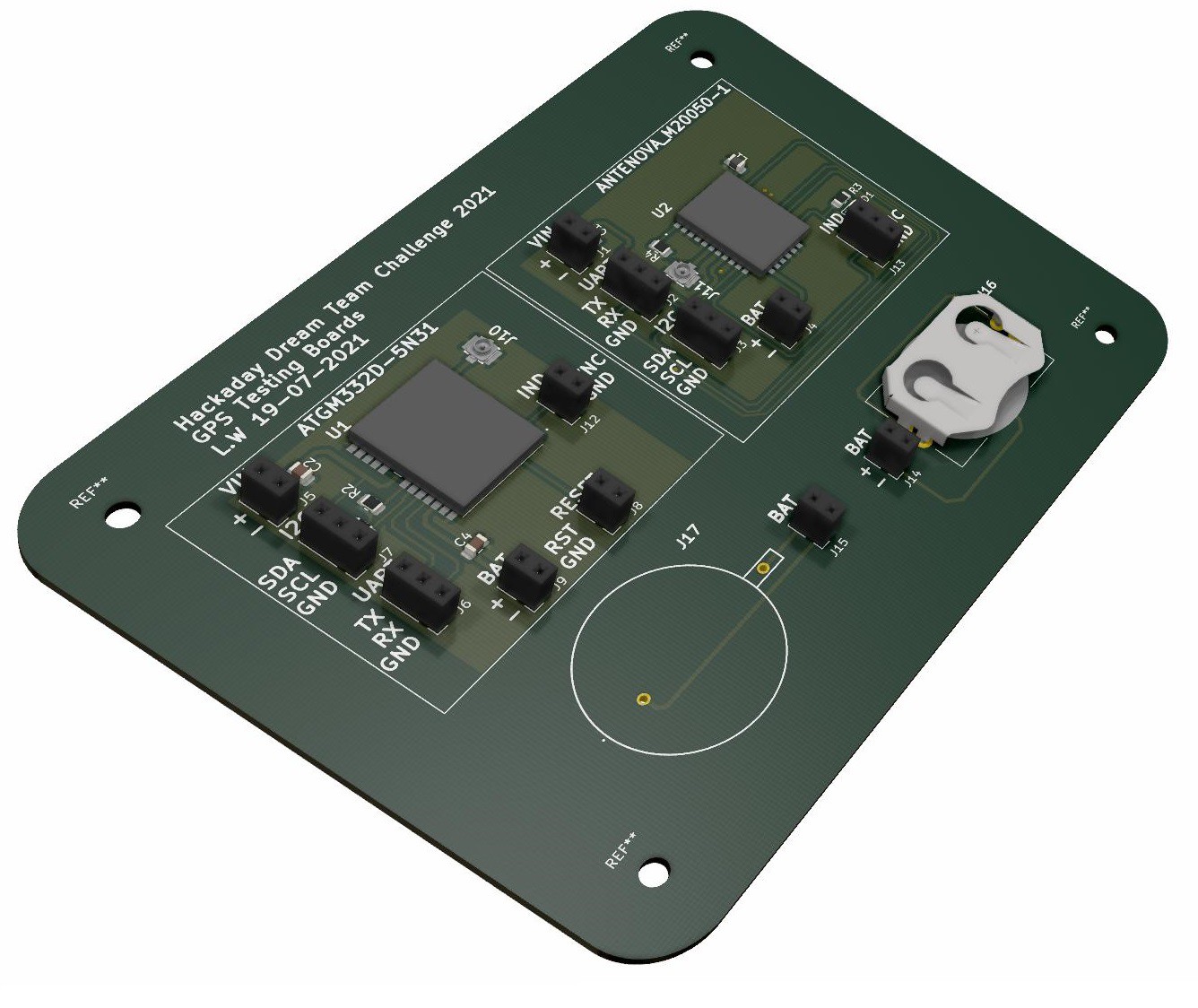
PCB
Discussions
Become a Hackaday.io Member
Create an account to leave a comment. Already have an account? Log In.