 Randy Elwin
Background:
As with many DIY projects this one started simple – adding a case fan to a Small Form Factor (SFF) desktop computer. The reason for adding a fan was to remove additional heat from an overclocked GPU during occasional heavy loading.
SFF computers are typically compact, with no extras such as extra fan connectors or a place to add a case fan. However, there’s room on the back to hang a 80mm fan, and after fabbing a few aluminum clips the new case fan sits snugly over unused slots.
The case fan is easily powered by Tee-ing off the graphics card fan power connector, and as a bonus the case fan’s speed is now controlled by the graphics card, keeping fan noise down.

This arrangement worked great until a recent graphics card update. Unfortunately the new card’s fan power connectors are smaller and not very accessible. I would have to find some other means of spinning the case fan.
Rummaging through my spare parts box located a manual fan controller, but this means tweaking a knob or leaving the fan spinning constantly – not what I wanted.
Having no solution on hand (and not wanting to buy anything) I figured this warrants a quarantine-DIY project, specifically using an ATTiny85 (I already have a few chips) and the Arduino environment.
The project:
After a few false starts the most reliable option uses an IR emitter-detector to read the GPU’s fan speed, and setting the case fan’s speed based on a configurable map. For reference there’s quite a few Arduino projects out there using IR devices and being limited to whatever parts I have, the best device in this case is an IR photo-transistor and IR LED.
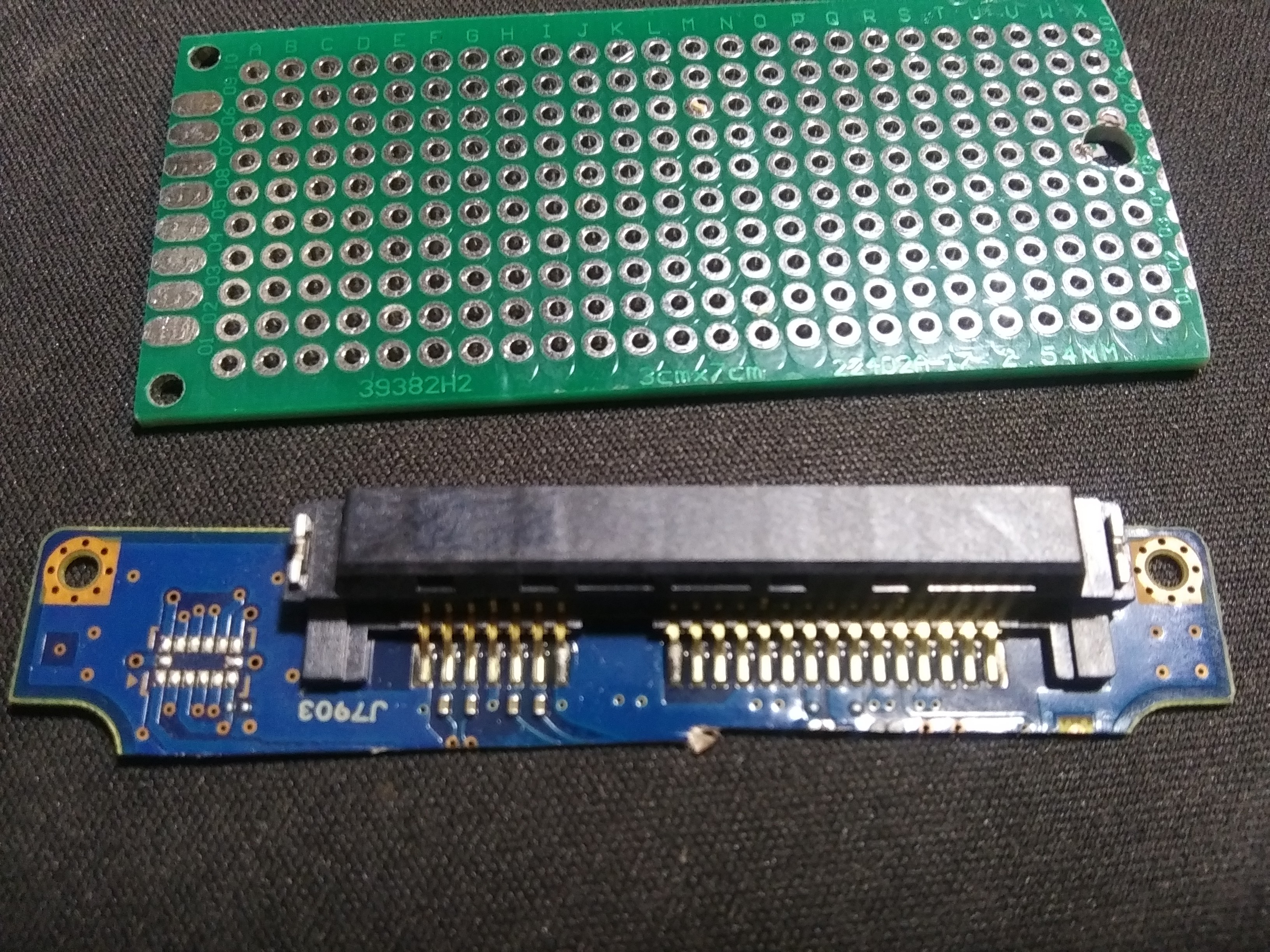
The emitter-detector sensor is mounted on a small perfboard and located inside the computer case with a small fridge magnet so that they point to a GPU fan.
The GPU fan has a holographic logo that the sensor reads but was sensitive to sensor placement, probably due to light scattering. A more reliable pattern disc made from a white mailing label ½ covered with aluminum tape is stuck to the fan center.


Operation Summary:
Mounted inside of a computer, the ATTiny’s photo-transistor senses pulses from the GPU’s fan rotation, and based on a configurable map stored in EEPROM, sends a PWM signal through a MOSFET to power the case fan. Serial communication provides monitoring and configuration.
Photo-transistor sensing:
ATTiny pin PB1 connects to the photo-transistor collector as well as biasing it with PB1’s internal pullup resister. PB1 is configured as analog comparator AIN1 and is configured to trigger an interrupt on AIN1 falling below the internal 1.1V reference. The Arduino library “analogComp” is useful for this configuration.
Case fan speed control:
Pin PB4 is configured as PWM OC1B output to a MOSFET. Using the standard Arduino “analogWrite()” can adjust fan speed but you’re not going to like the 490Hz tone emanating from the fan. One option is to push the PWM frequency above hearing range (20kHz) but this adds noise to the AIN1 sensing. The better option lowers the PWM frequency to under 60Hz. However, at slow fan speeds you’ll hear a “cogging” sound. This sound goes away with the addition of a 100uF cap to smooth the PWM signal. As implemented the PWM frequency is 30Hz. The 2N7000 MOSFET has a built-in flyback diode, which is helpful when pulsing fan motors. The fan operates below the MOSFET’s power rating.
Blinky LED:
Every ATTiny project needs one and this is no exception. This LED helps when positioning the sensor as the LED blinks when the sensor triggers.
Serial Comm:
The SoftwareSerial library provides for a service menu and reporting, and enables configuring operation. This library dictates the ATTiny runs at 8MHz. I use a 5V to RS232 adapter on a serial...
Read more »


 WJCarpenter
 Est
Est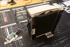
 Mikael 'abbe' Albertsson