 James Wilson
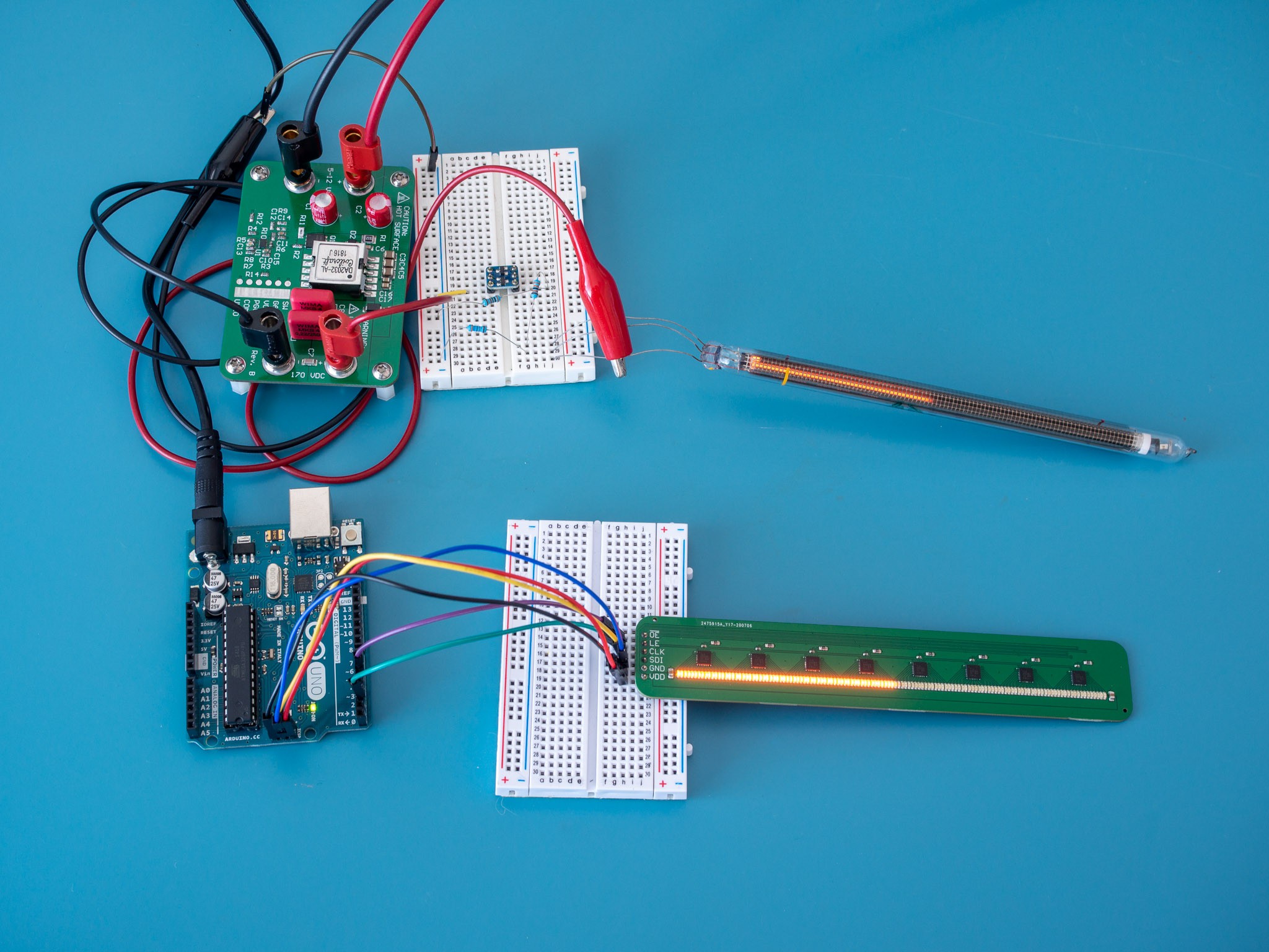
Two of the lesser-known Nixie tubes are the IN-9 and IN-13 bargraph indicators. Instead of being digital numeric displays, these are analog linear indicators where the length of the glow discharge is proportional to the current.
While aesthetically pleasing, Nixie tubes have some disadvantages:
- They require a high-voltage power supply. If the tube is being controlled by a microcontroller, a discrete driver circuit is also required to isolate the Nixie tube cathode from the microcontroller and create a adjustable current source to drive the tube.
- The relationship between current and length of the glow discharge is nonlinear, and shows some variation between units, which may require tuning and trimming. Lines are marked in paint on the side of the tube, between which the display is guaranteed to be linear ±10%.
- With the exception of some artisanal manufacturers, Nixie tubes aren't being made anymore. The supply of surplus Nixie tubes will continue to dry up and prices can be expected to rise. As of the time of writing, IN-13 tubes cost 8-10 USD each in small lots.
While bargraph LED modules are available, they usually only offer 8-12 steps of resolution and the LEDs are quite large and spaced generously. They aren't a good substitute for the continuous and infinitesimally adjustable line that you get from a IN-9 or IN-13.
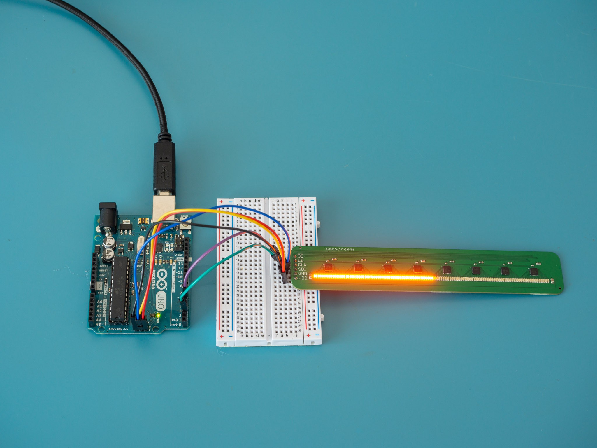
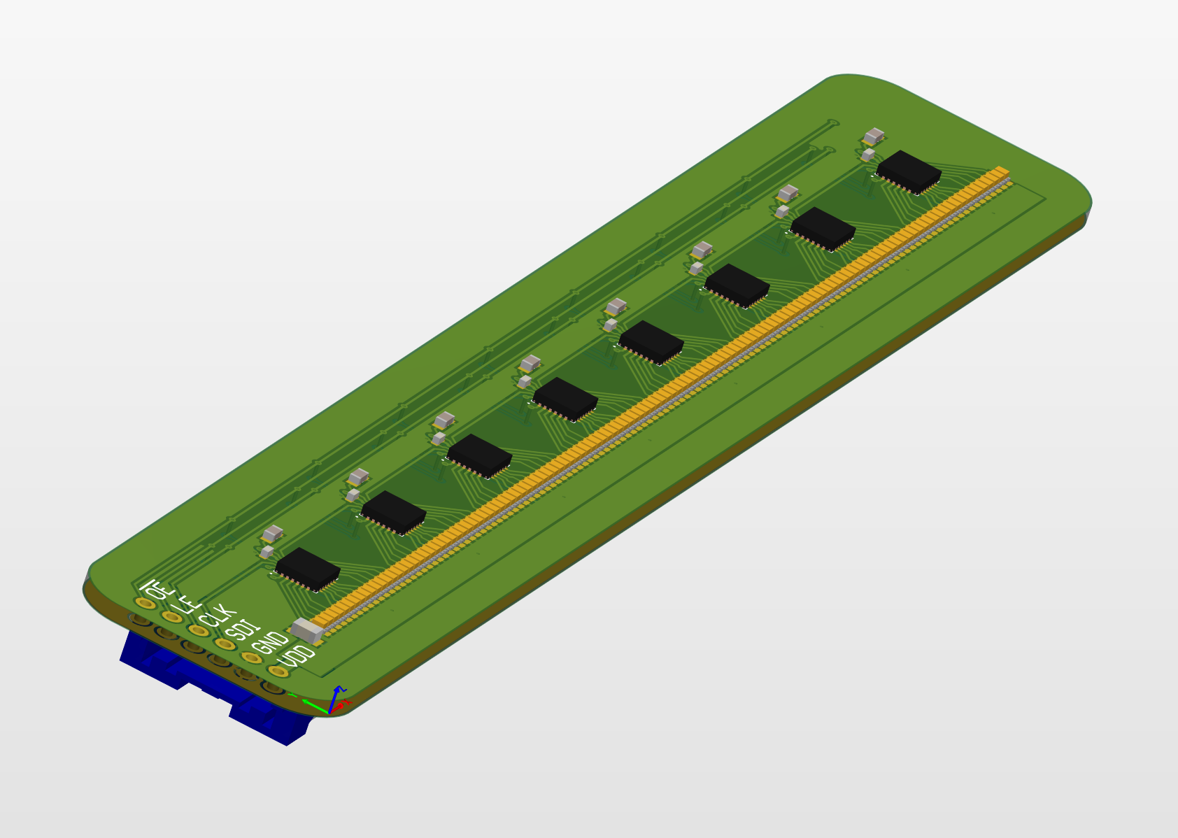
This design combines densely-placed SMD LEDs and shift registers to create a linear indicator that is easy to control from microcontrollers. A shift register makes it possible to control 100 LEDs without needing 100 pins. All that is required is to send the shift register a string of bits, for example, 10000001 to indicate the first and last LEDs should be lit. The shift register holds its state until new data is received, meaning the display does not need to be continually refreshed.
In detail, the shift register requires three pins: a clock (CLK), serial data in (SDI), and latch enable (LE). Data is read from the SDI line on the rising edges of the clock. After the string is finished, pulsing the LE line will make the current values in the shift register effective in driving the LEDs. Most microcontrollers provide built-in serial peripheral interface (SPI) controllers that can generate the clock and serial data signals.


 Ben Patterson
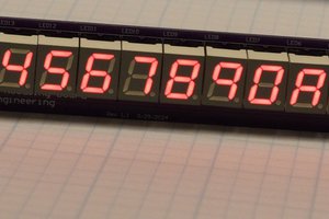
 Bharbour
 burkethos
 Ken Yap
I like this idea, should be useful. Do you think you'll have any problems keeping the LEDs aligned during soldering? Seems like a crooked one would ruin the look.