0%
0%
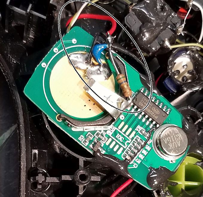
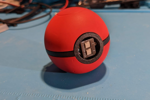
Adaptive wireless switch
Adaptive switches are often used by people with limited hand function. This switch looks like a game controller and uses a low cost keyfob.
 Andrew Mitz
Become a Hackaday.io member
Already have an account? Log in.
Just one more thing
To make the experience fit your profile, pick a username and tell us what interests you.
Pick an awesome username
hackaday.io/
Your profile's URL: hackaday.io/username. Max 25 alphanumeric characters.
Pick a few interests
Projects that share your interests
People that share your interests
 Gertlex
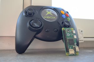
 JT
JT
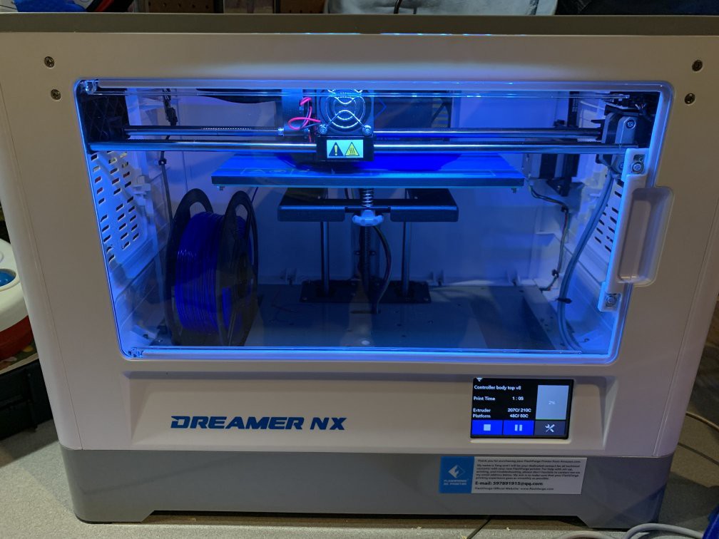
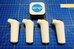
3D printing was done on a Flashforge Dreamer NX.