 Andrew Mitz
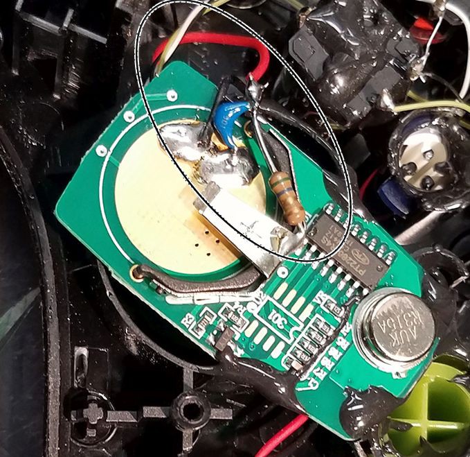
I found two controllers that did not properly trigger the receiver. I saw a similar problem with a non-rechargeable controller I built earlier. The keyfob board is designed to work with coin cells. When you use a separate power source it lacks a low impedance pathway across the battery terminals. To solve this, I added a 1.0 uF ceramic capacitor across the keyfob battery terminals. The picture shows a capacitor with a 5.6 ohm resistor. The resistor was needed in that earlier design because it had two large 3 volt coin batteries. The 6 volts was too high, so the resistor helped increase the source resistance. Using the capacitor, alone, fixed the problem in the new controller. Some controllers don't need the capacitor, but I don't think the capacitor can hurt.
Discussions
Become a Hackaday.io Member
Create an account to leave a comment. Already have an account? Log In.