 Miguel Fernández
After a
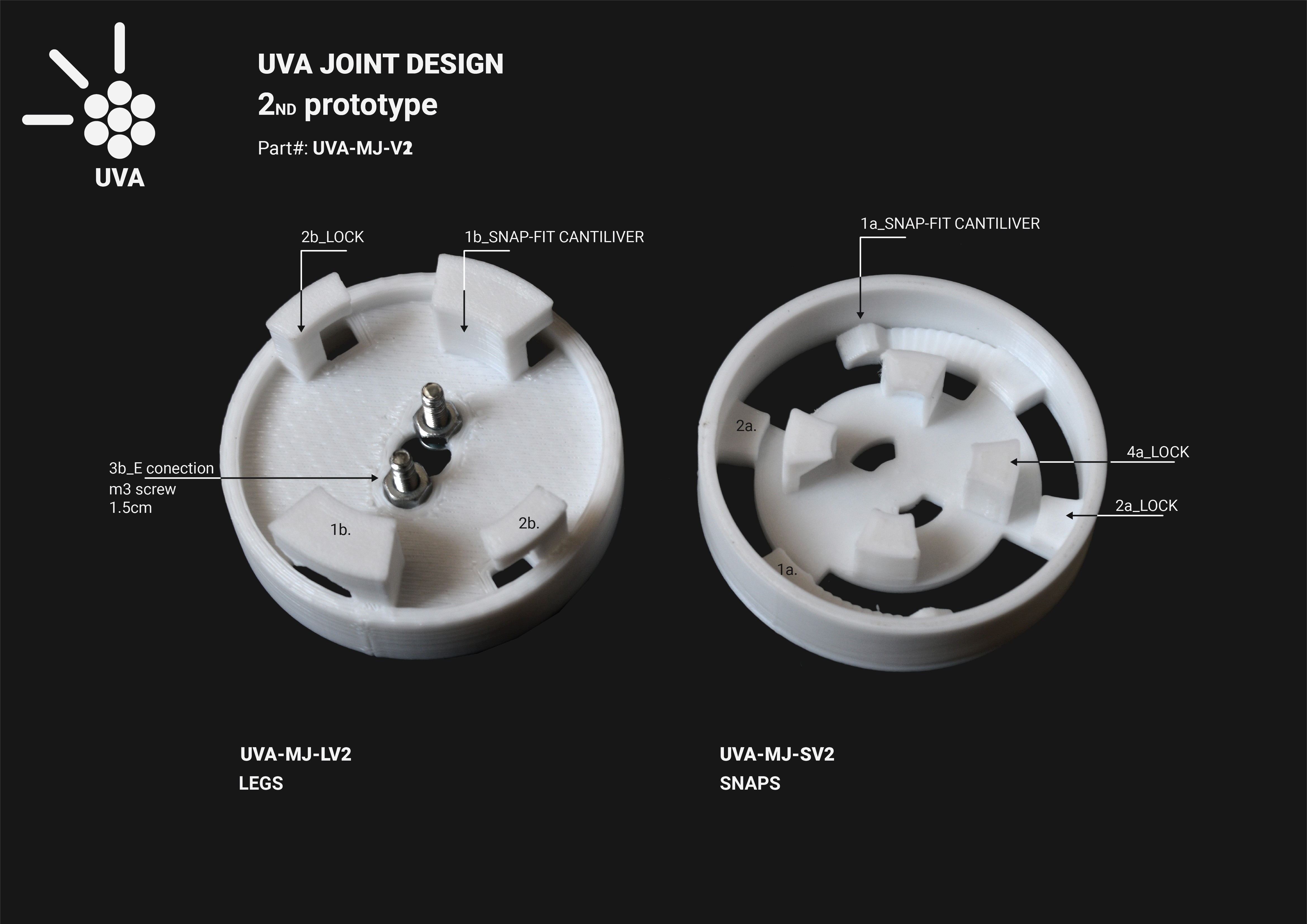
lot of tests and fails with UVA joint V1, we have developed a second version
that solves the weaknesses of the first attempt. The main fail with the V1 was
in the snap-fit cantilever connection in the legs ring (UVA-MJ-LV1_1b). This
is the part of the joint that will be attached to the tool.

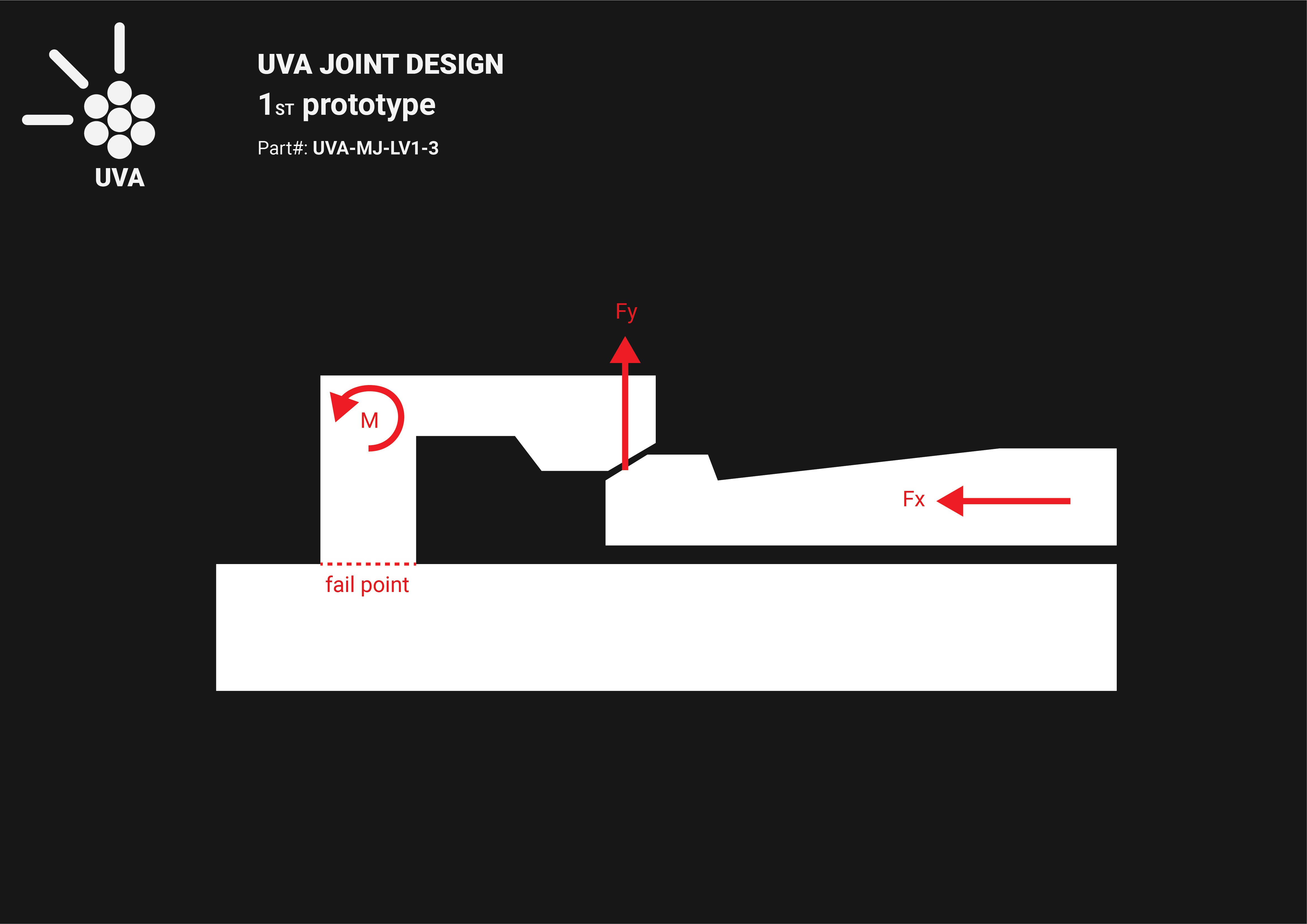
As you can see in the pictures it failed because of the lack of stiffness in the legs. The vertical force practised by the bending piece "1a" in the snaps ring at the moment of snapping also bent the legs in the legs ring. This part wasn't either design or prepare to bend. Because of the way that FDM 3d printed pieces work, the maximum flex and bend resistance is achieved parallel to the layers. In this case, the force applied to the leg was perpendicular to the layers and, after some attempts to connect both rings, the piece failed and break in the joint between the plastic layers.
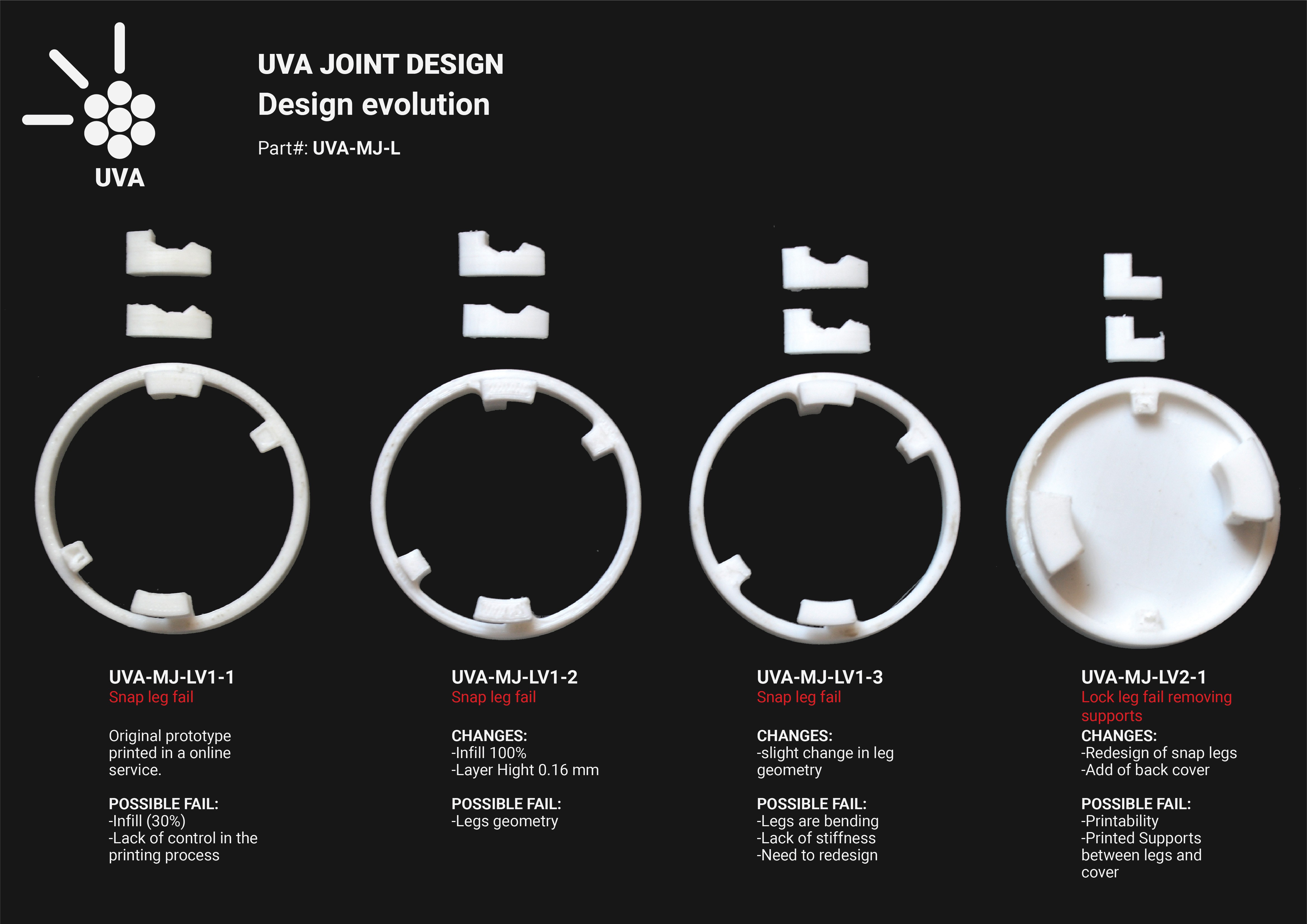
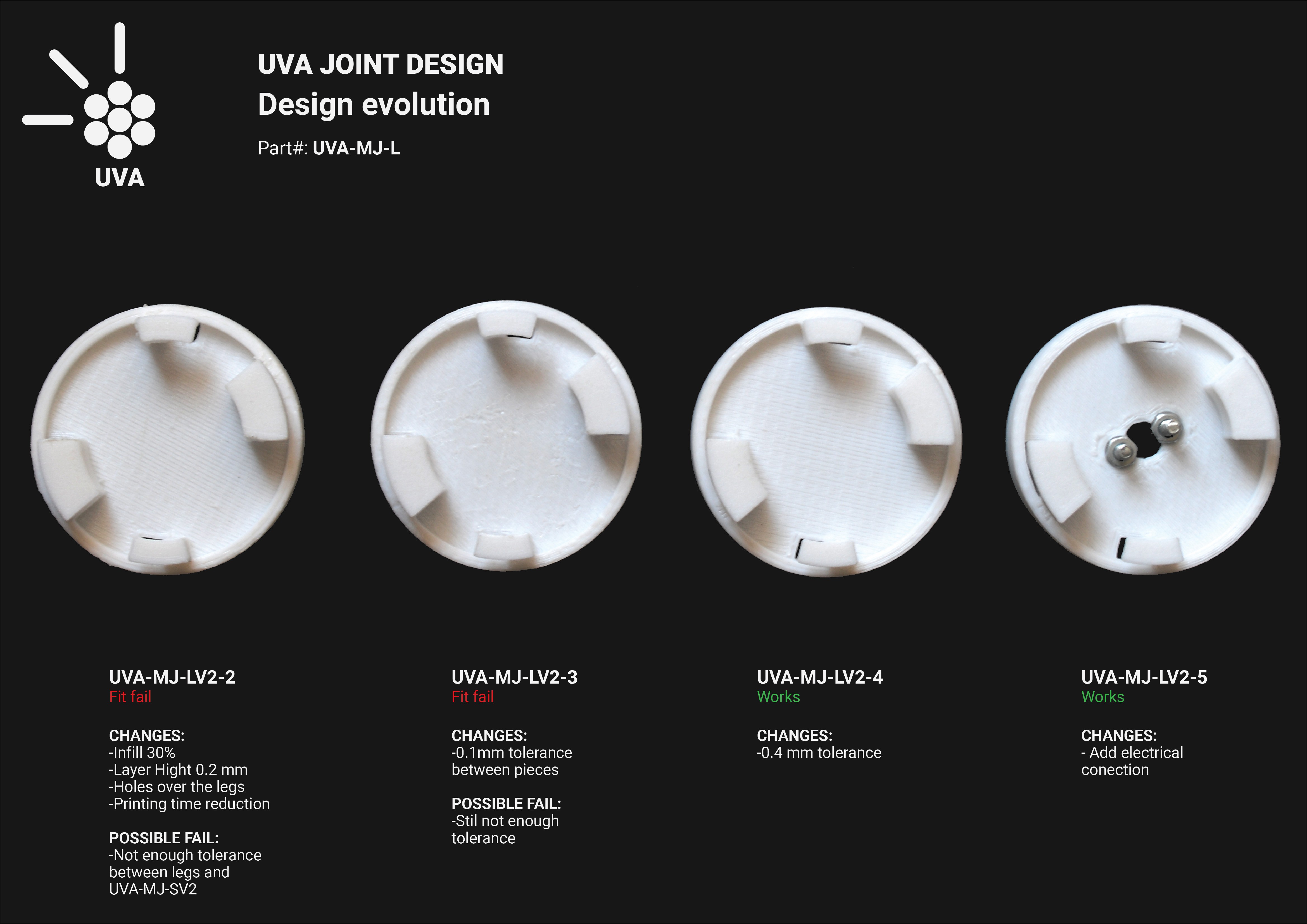
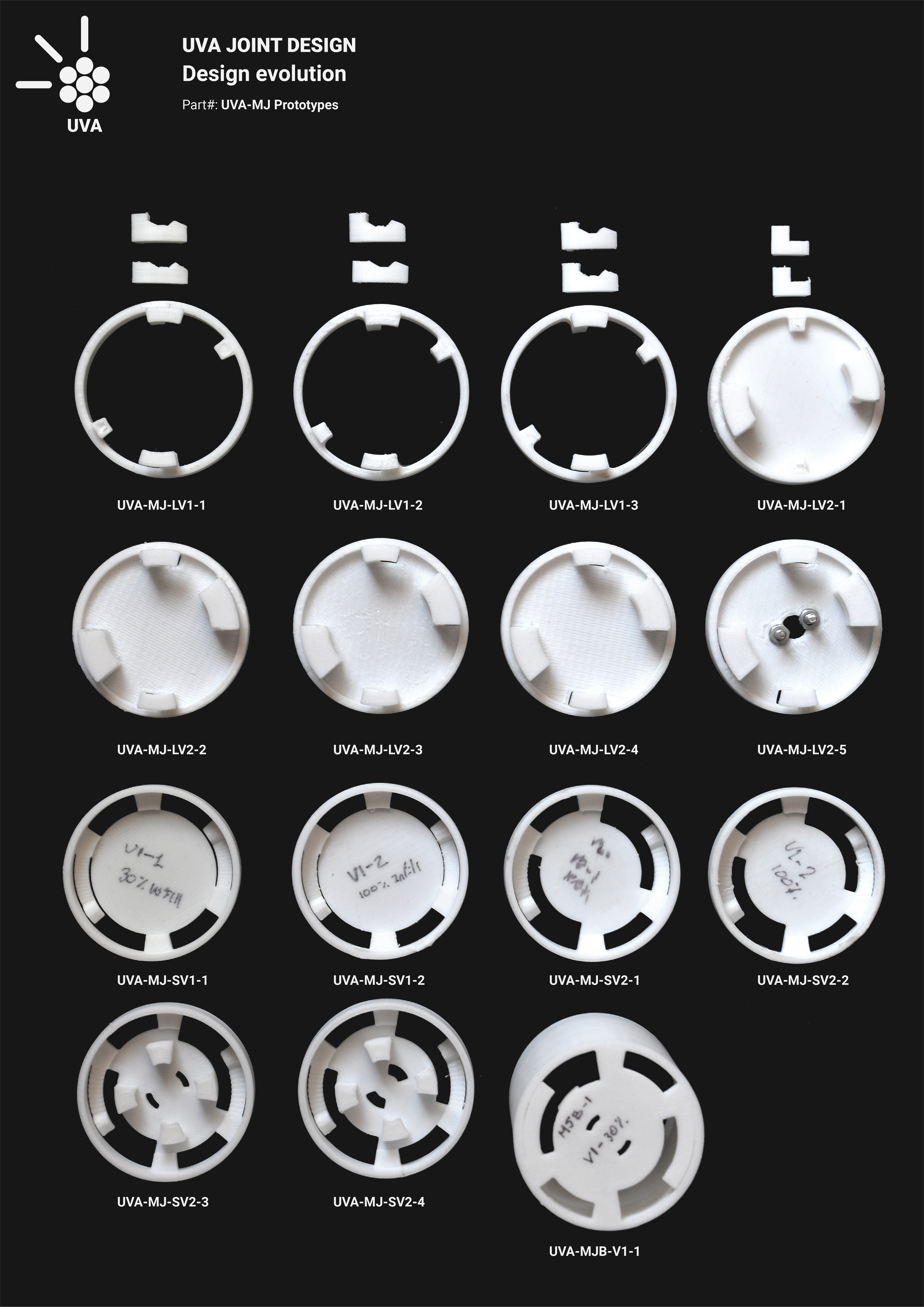
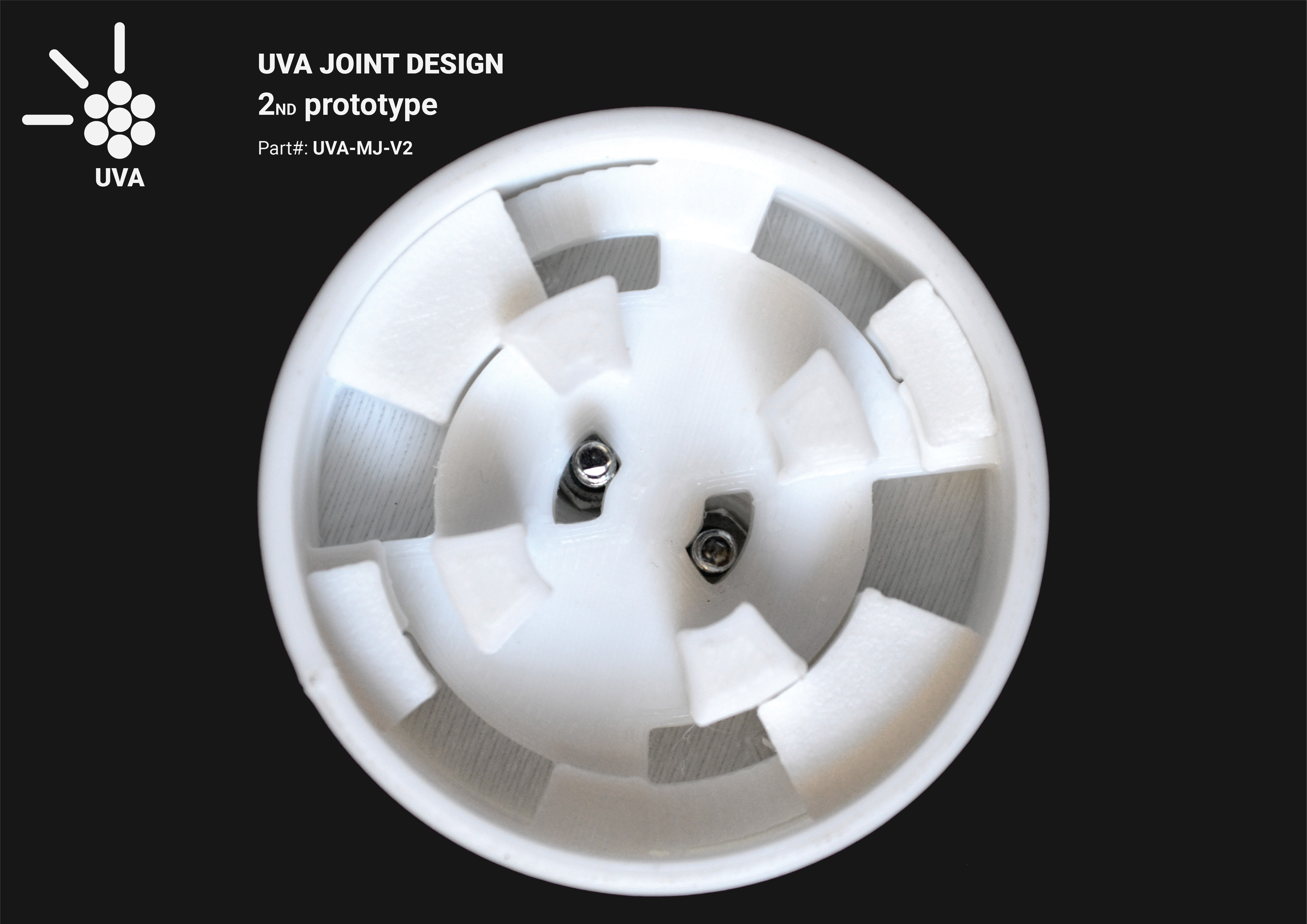
In the UVA Joint V2 (UVA-MJ-V2) we increased the area of the legs to achieve the necessary stiffness to prevent bending and also to increase the surface of contact between the layers. With the new solution came some new problems, mainly related to the printing process. The leg parts both snap-fit and locks have to fit in the snap parts with not too much tolerance to guarantee a good joint. So the termination of those has to be very precise and it is necessary to avoid supports to print the legs. As you can see, we left some holes over the legs to guarantee a qualitative termination.
Furthermore, we already took the next step and designed the electrical connection in the legs ring, and we are really close to finished the battery pack design but it will be discussed in another log.
Discussions
Become a Hackaday.io Member
Create an account to leave a comment. Already have an account? Log In.