 Said Alvarado Marin
Since the UV flashlight has so many sensors, it requires a Microcontroller to read and manage everything. Of course, using the ever ubiquitous Arduino UNO chip ATmega328p is the obvious choice. As it greatly simplifies software compatibility later on. and this project doesn't really need anything more powerful.
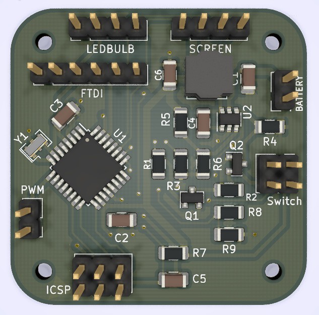
This board has a lot connections and parts, so let's do a breakdown and look at each of them.
Power Regulator
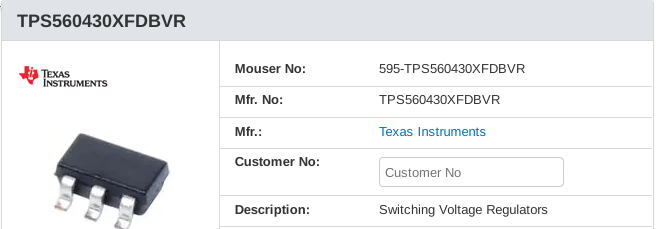
- Inexpensive
- Low part count
- NON-QFN package (for easier soldering)
- The datasheet already pre-computes the entire circuit for a 3.3v ouput, so I didn't have to do any calculations. :D
Switch latch circuit
The main power on switch had a rather convoluted latch circuit to allow both the Arduino and the user to activate the main regulator's ENABLE pin. So that if a tactile button was used, the Arduino could remain ON even after the button was released.
It was taken from this website: https://circuitjournal.com/arduino-auto-power-off
It's still there in the circuit, but we found a switch that latches ON after being pressed, so the functionality wasn't needed.
Battery monitor
R8 and R9 form a voltage divider that allows the Arduino to measure the battery voltage. It's not a very precise method to estimate the remaining percentage of charge of the battery. But it is enough to provide a rough estimate of when the battery is too low. This way the Arduino can shut the LED's off and protect the battery from over discharging.
OLED Screen
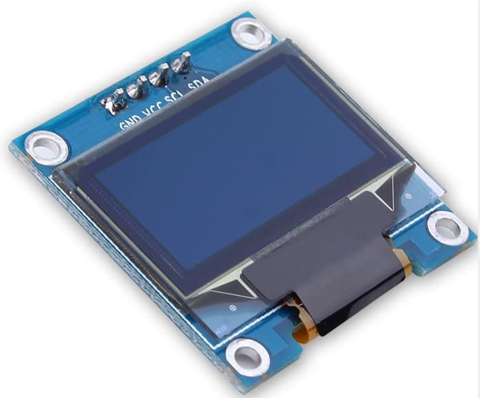
This is a little generic 128x64 0.96" Black & White OLED screen powered by a SSD1306 chip. They are widely available and have extensive software support.
Resonator
A crystal with a frequency of 12MHz was chosen for this board. Why the weird frequency? Because the ATMega328p can be unstable at 3.3v with a 16Mhz crystal. But 8Mhz is too slow for this application. So the fastest crystal we can use in this case is a 12Mhz one.
Programing connector
The board has 2 programming connectors. A ICSP connector to program the chip through SPI, and a Serial FTDI connector to program it through Serial.
However, for small incompatibility problems between the Arduino bootloader and an ATMEGA328p with a 12Mhz crystal (As is the case here). Right now, only the ICSP connector works.
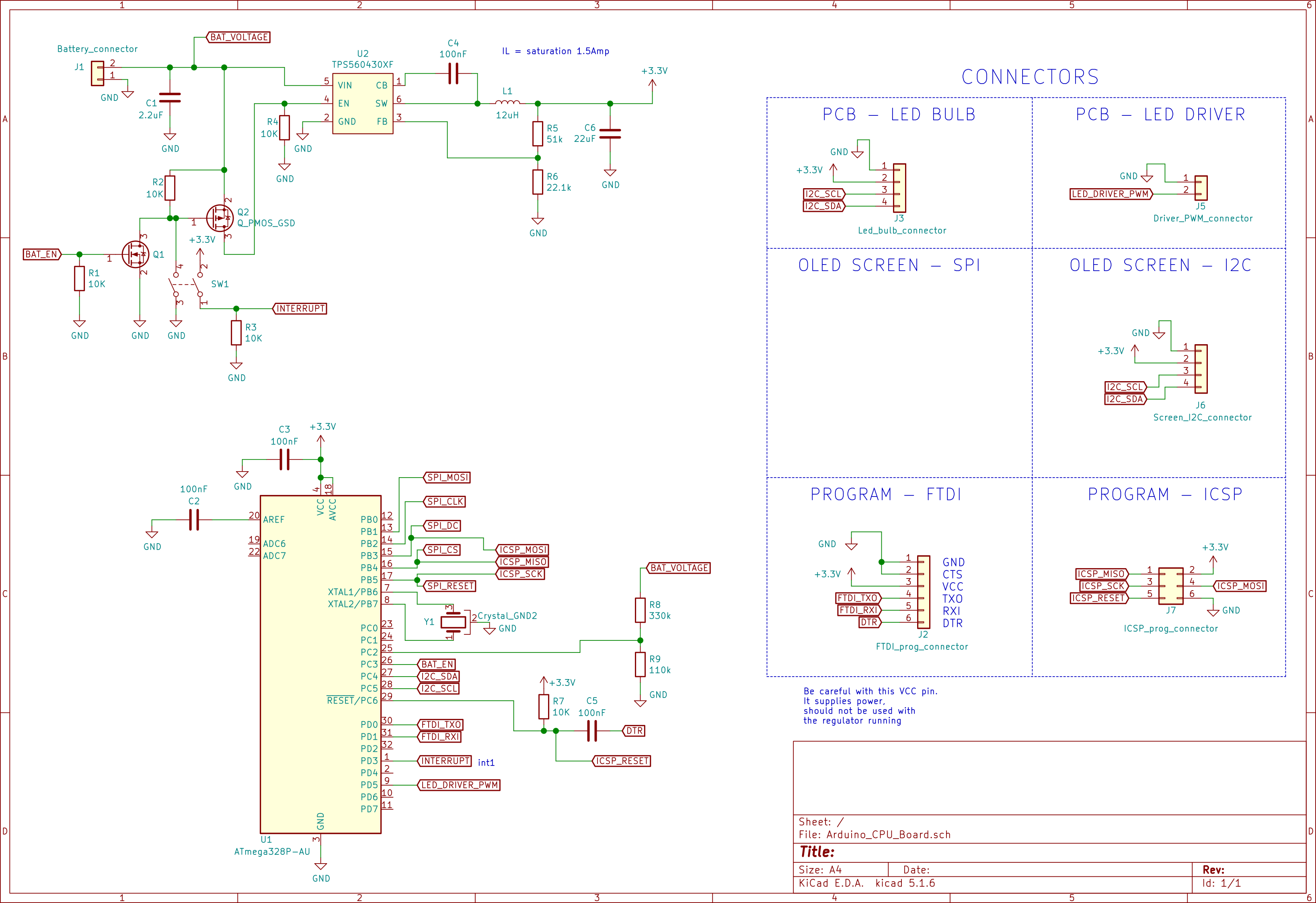
Full schematics
Here is the full schematics of the board, if you can also find here the full Bll of Materials,
Discussions
Become a Hackaday.io Member
Create an account to leave a comment. Already have an account? Log In.