 Michael Gardi
The core of a Turing machine is the Finite State Machine, a finite set of instructions that, given the state the machine is currently in and the symbol it is reading on the tape (symbol currently under the head), tells the machine how to transition to the next state of the computation. These Finite State Machines are usually described in one of two ways. As state transition diagrams:
or as state transition tables:
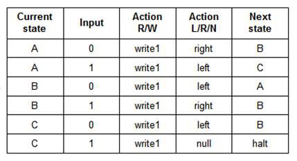
Both of the above describe the same 3-state 2-symbol "busy beaver" program.
When building a Turing Machine, these definitions must somehow be manifested in a way that the machine can understand them. I have seen these state transitions encoded onto paper tape or expressed as pegs on a 2-dimensional board. Since this project is supposed to be a Turing Machine Demonstrator I wanted this "translation" to be as simple as possible. Then it struck me, "What if the state transition table and the Finite State Machine input were one in the same?".
State Machine Setup
So this is what the input area for TMD-1 will look like, a state transition table.
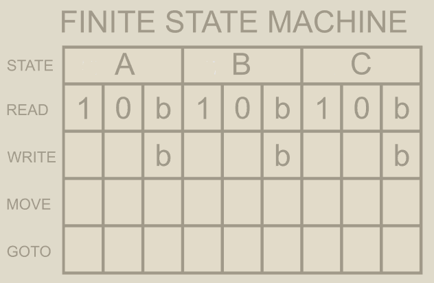
The blank boxes in the table above will have shallow rectangular depressions into which appropriately labeled "tiles" can be set: 1/0 for Write, L/R for Move, and A/B/C/H for Goto. TMG-1 will be able to "read" these tiles to determine the definition of the state machine. I'm calling this my "Azul" interface based on the name of the popular tile based board game.
Reading Tiles
Once I determine how I wanted the Finite State Machine input to work, I had to figure out how to make it work. My first idea was to use magnetic reed switches, but I had been looking for an excuse to play around with Hall Effect Sensors. So I ordered some SS451A Omnipolar Magnetic Switches from Digi-Key.
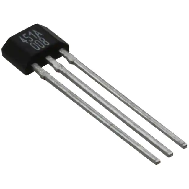
I guess I shouldn't have been, but when they arrived I was surprised at how small these components were. I chose the omnipolar part because I didn't want to have to worry about the polarity of the "triggering" magnets.
I setup a test. First I secured one of the sensors to the back of a small panel that I printed to represent a tile input square on my state machine.
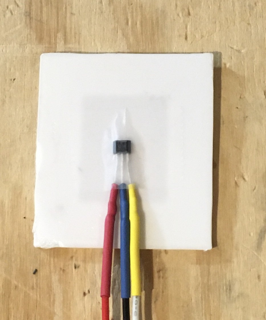
I connected this to an Arduino so that when the sensor was triggered an LED would light. Then I printed a couple of test tiles.

The tile with the "1" has a small 3 mm x 1.5 mm magnet embedded .6 mm from the bottom and centered in the tile, while the "0" tile has no magnet. Here is my first test:
Testing showed that the hall effect sensor can clearly be triggered by some very small magnets embedded into the tiles. Furthermore I found that the magnet must be lined up within a few millimetres of the central axis if the sensor. This is a good thing because it means that multiple sensors can be embedded within a small area (the tiles are only 20 mm x 25 mm) without the risk of interfering with each other.
Tiles will be identified based on their row and "magnetic" signature. So tiles placed in the Write row will be considered to a 0 or 1 based on the absence or presence of an embedded magnet. Similarly the Move row will assume the placement of R and L tiles. The Goto row must recognize four different tiles (A, B, C, and H) so two magnet positions will be used to create four unique identities.
Since the parts themselves are so small and to ensure that they line up correctly with the input squares on the Finite State Machine transition table I created a PCB "reader" board.
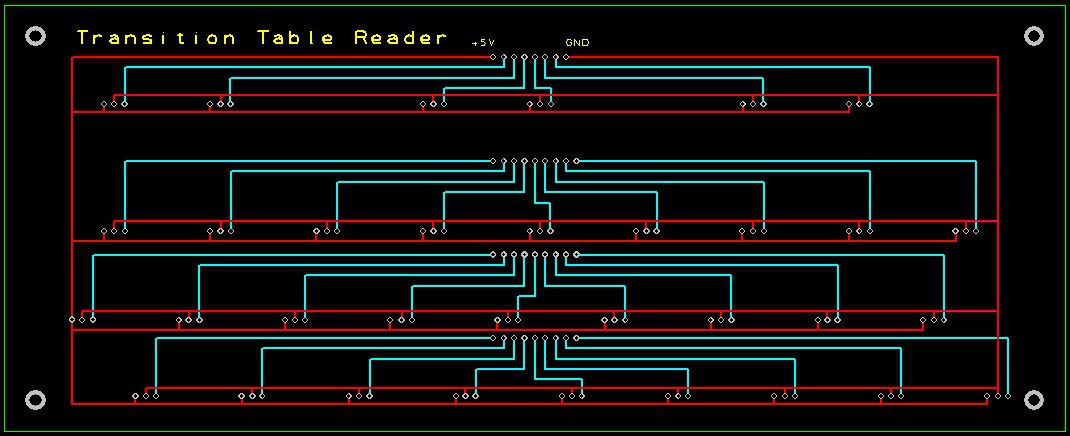
This will be mounted directly below the input area of the transition table. It should be back from the fab in a few days or so now.
So the user will be able to "program" TMD-1 by simply using tiles to "fill out" a state transition table for the Finite State Machine. I don't think it gets much easier than that.
Discussions
Become a Hackaday.io Member
Create an account to leave a comment. Already have an account? Log In.