 Michael Gardi
Wire Wrangling
At the same time that I was having the Transition Table Reader board made I had a small PCB done to help wrangle the wires from the eight servos.
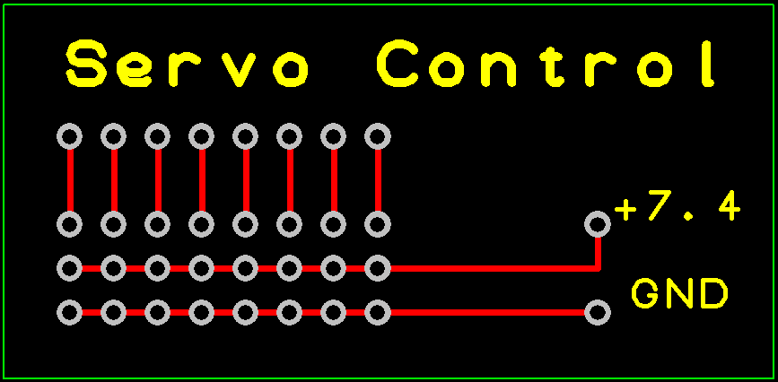
I just added headers to allow me to plug the servo connectors into the board with the PWM signals brought out.
Not Enough Pins
Now you would think that since I am using an Arduino Mega there would be enough I/O pins to go around. The Mega has 54 I/O pins plus the 16 Analog pins can be used as digital I/O for a total of 70! Well it turns out I need 74 in total. The breakdown:
- 27 outputs for LEDs
- 33 inputs for Hall Effect sensors
- 8 outputs for Servos
- 6 inputs for buttons and switches
I could have used a Charlieplexing Matrix for the LEDs and a Keyboard Matrix scheme for the sensors but that would have made my programming job that much harder.
Instead I chose to use a couple of 16 Channel GPIO Expanders based on the MCP23017 part.
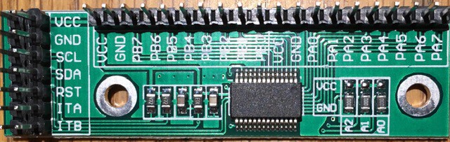
I'll use one for the 10 LEDs and 4 buttons on the Tape Panel, and the other for all 16 LEDs on the Finite State Machine Panel. Using these also has the advantage of "localizing" some of the wiring making for a neater job. It's also nice that they have extra VCC and GND pins in addition to doubling up on the control pins making wiring easier.
Wiring the Tape Panel
I started by joining all of the ground leads together for the LEDs and buttons then added a jumper so I could attach the grounds to one of the expander's extra GND pins.
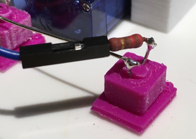
To the LED anodes and the normally OFF terminal of the push buttons I attached jumper cables with female connectors to mate with the expander. I also added 220 R limiting resistors to the LEDs.
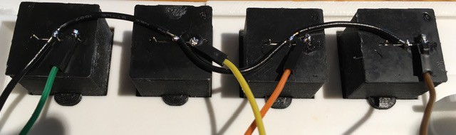
I mounted the Servo Control And Expander PCBs to the inside of the Tape Panel Box part of the frame using two sided tape.

The following connections were made:
| From | To |
|---|---|
| Servo 3 pin connectors from left to right. | Servo Control left to right (middle to edge of board). Make sure that the leads have the proper orientation. |
| LEDs from left to right. | Extender Pins: PA7, P A6, PA5, PA4, PA3, PA2, PA1, PA0, PB0, PB1 |
| Move Right Button | Extender Pin: PB7 |
| I/O (Flip Bit) Button | Extender Pin: PB6 |
| Move Left Button | Extender Pin: PB5 |
| Reset Button | Extender Pin: PB4 |
| Tape Panel: GND | Extender Pin: GND |
| Servo Control Pin: VCC | Extender Pin: VCC |
| Servo Control Pin: GND | Extender Pin: GND |
Connecting to the Arduino
I mounted the Arduino below the Tape Panel boards to a reinforcing cross bar that I had added to the console again using two sided tape.
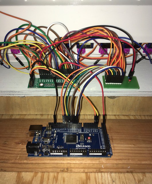
The following connections were made:
| From | To |
|---|---|
| Servo Control PMW pins left to right. | Arduino Pins: 2, 3, 4, 5, 6, 7, 8, 9 |
| Extender Pin: GND | Arduino Pin: GND |
| Extender Pin: VCC | Arduino Pin: VCC |
| Extender Pin: SCL | Arduino Pin: SCL (21) |
| Extender Pin: SDA | Arduino Pin: SDA (20) |
Done Wiring
That's it. The Tape Panel is completely wired up and ready for testing.
Discussions
Become a Hackaday.io Member
Create an account to leave a comment. Already have an account? Log In.