 hesam.moshiri
Results
Figure below shows the wiring diagram of the AC Dimmer. If you intended to check the output waveform using an oscilloscope, you must not connect your oscilloscope probe’s ground lead to the dimmer output or nowhere on the mains.
Attention: Never connect your oscilloscope probe directly to the mains. The probe’s ground lead can build a closed loop with the mains terminal. It would blow up everything in the path, including your circuit, probe, oscilloscope, or even yourself!

To overcome this problem, you have 3 options. Using a differential probe, using a floating oscilloscope (the majority of the oscilloscopes are ground referenced), using a 220V-220V isolation transformer, or just simply use a cheap step-down transformer, such as 220V-6V or 220V-12V … etc. In the video and figure-11, I used the last method (step-down transformer) to check the output.
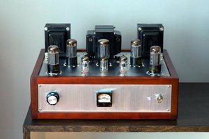
Figure below shows the complete AC dimmer unit. I’ve connected two boards using a 14-way flat wire.

Figure below shows the zero-crossing points and the Triac’s ON/OFF time. As it is clear, both the rising/falling edge of a pulse was considered to not to face any flickering and instability.


 Justin Scott
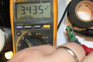
 Zach Scheidegger
 Discrete Electronics Guy
So looks like a leading edge dimmer. Did you also consider a trailing edge design? I'm currently incorporating a multi-channel design in my current project ( https://hackaday.io/project/174098-lighting-color-control-with-commodity-lamps ). I'm most interested in seeing more development in multi-channel trailing edge designs as these tend to have the highest compatibility with the kinds of loads under consideration for my team's design (AC dimmable LED lamps). However, I'm otherwise very interested in the idea of an addressable, microcontroller driven AC dimmer as this is a core component of the project.
I would also like to read more about how you chose to map the different output levels to the effective dimming level (linear, logarithmic, something else?).
Good luck!