0%
0%
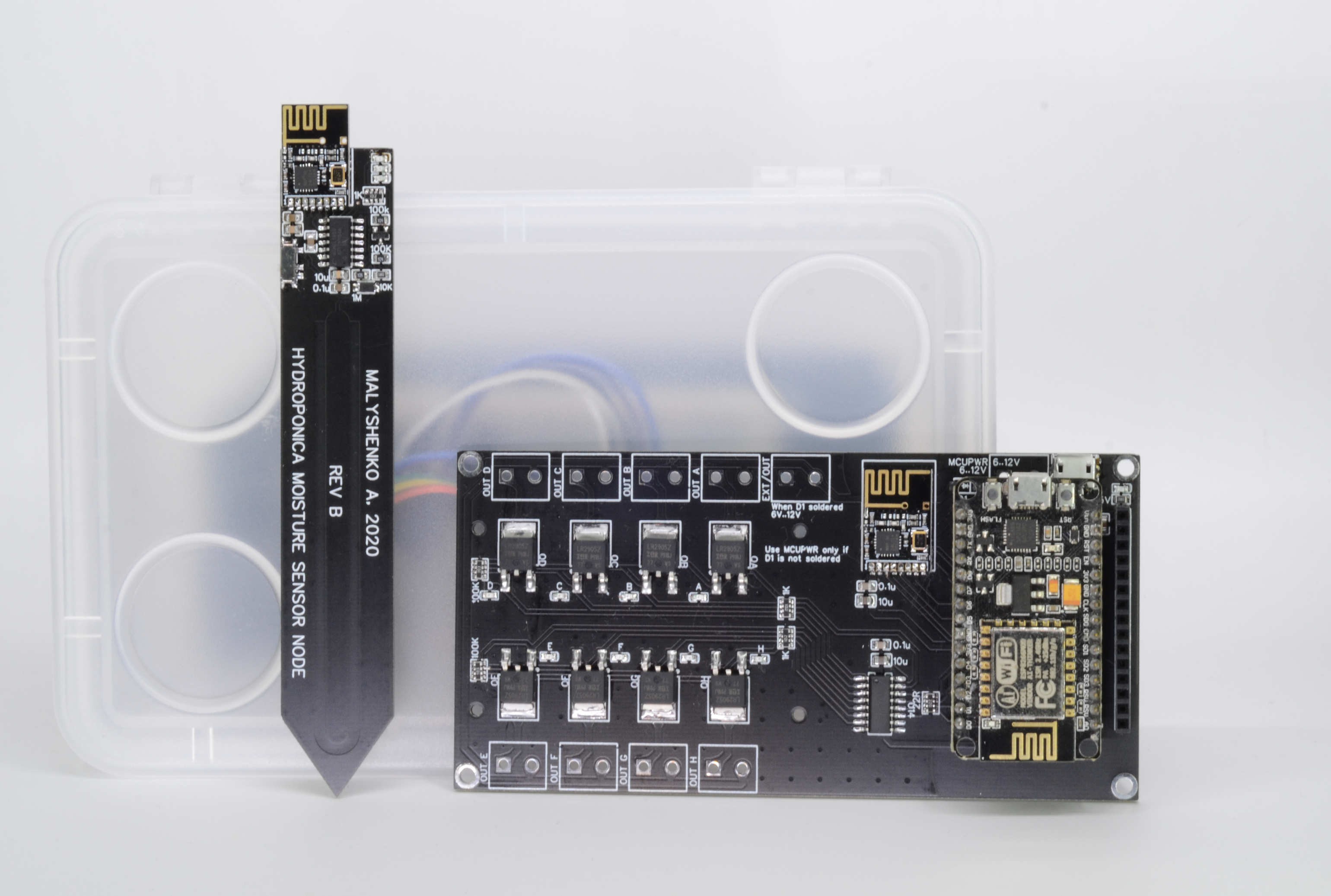
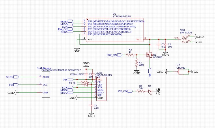
Wireless soil moisture sensor
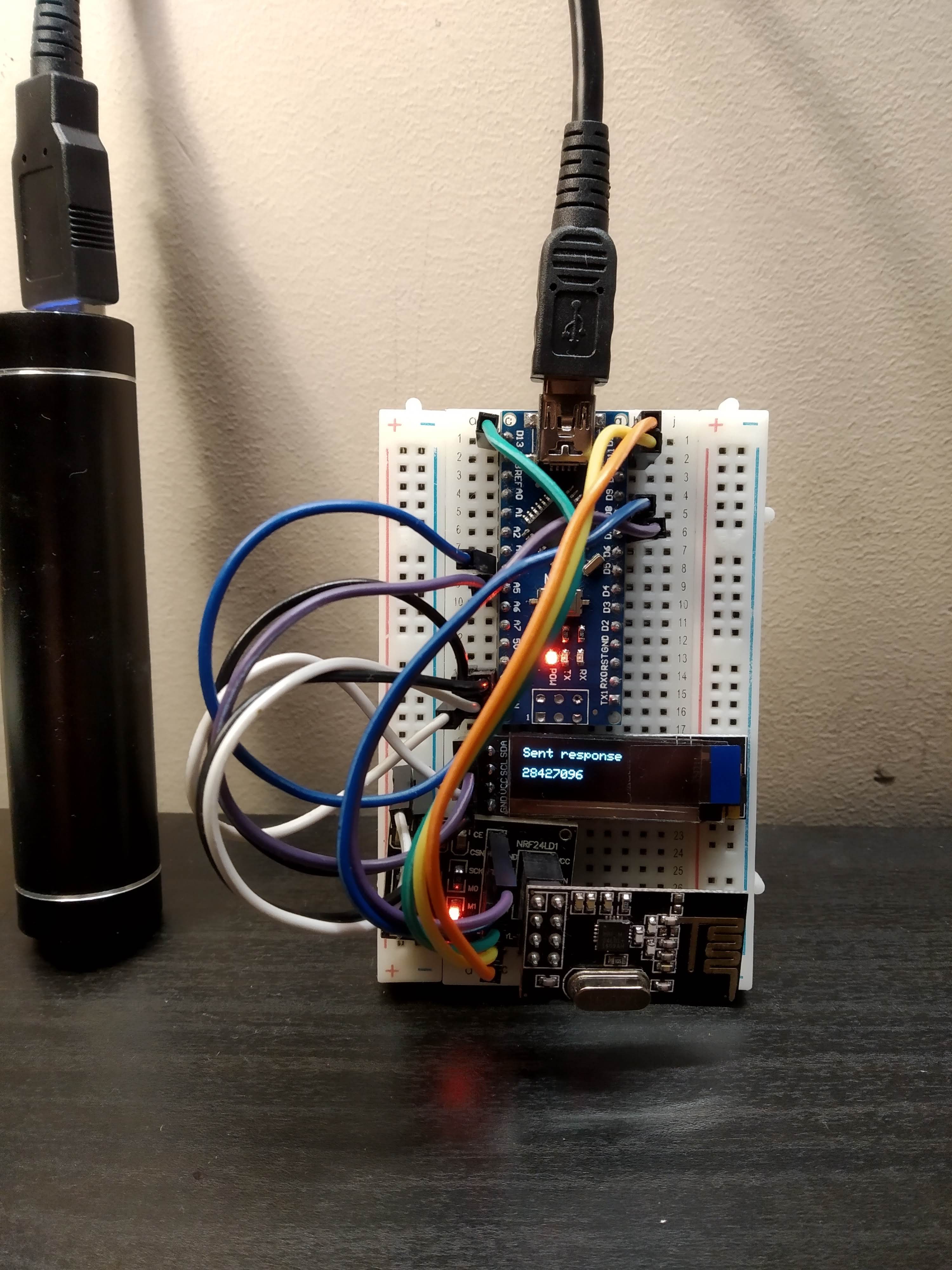
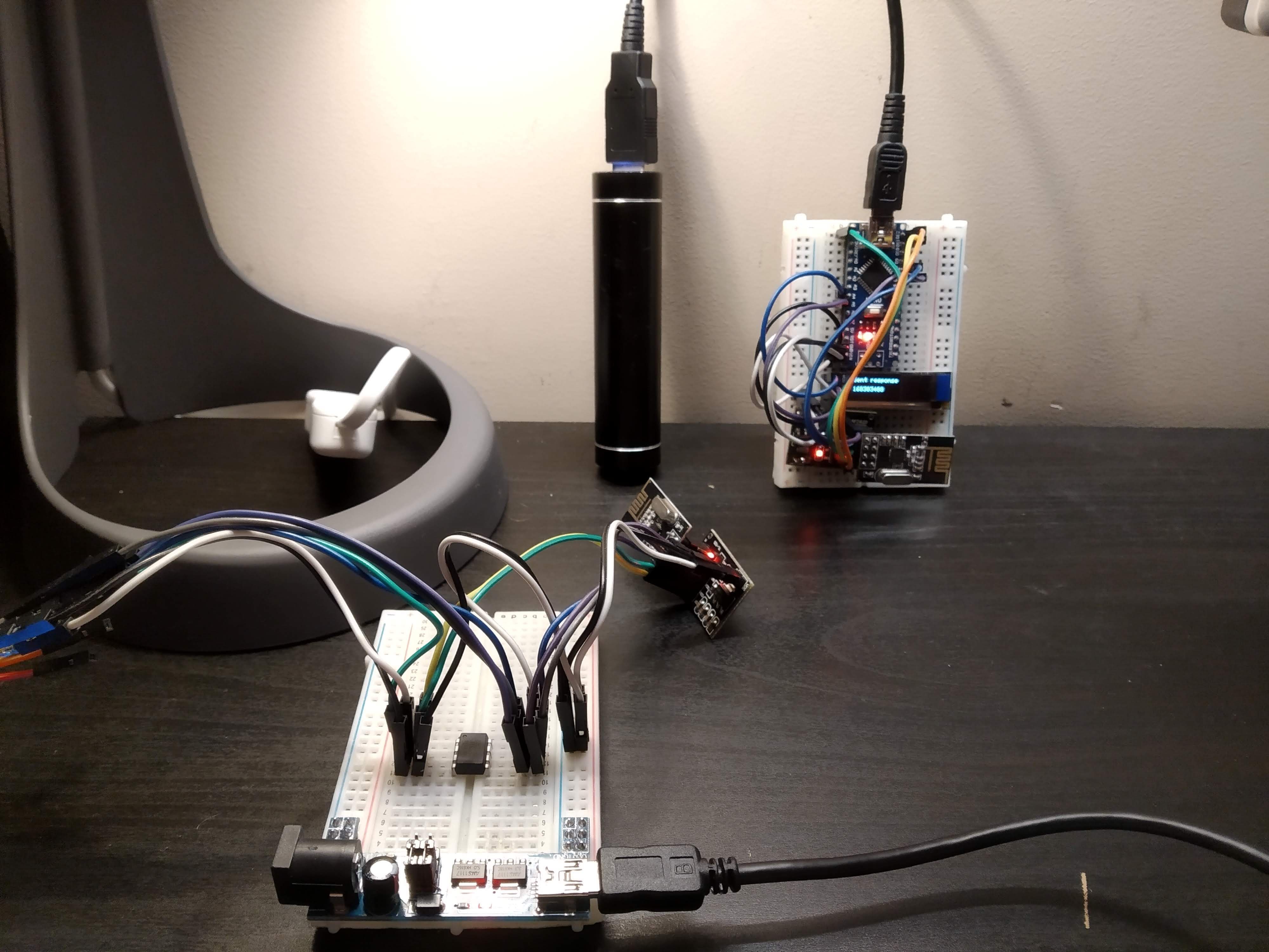
NRF24L01 ATTINY85 work together to measure and broadcast soil moisture sensor data
 andriy.malyshenko
Become a Hackaday.io member
Already have an account? Log in.
Just one more thing
To make the experience fit your profile, pick a username and tell us what interests you.
Pick an awesome username
hackaday.io/
Your profile's URL: hackaday.io/username. Max 25 alphanumeric characters.
Pick a few interests
Projects that share your interests
People that share your interests

 davedarko
 Estudio Roble
 Sagar 001
 Flo
Flo
I made something very similar to this. My solution was to use the sensor probe with the LMC555 cmos version of the 555, this can be powered directly using the output from an esp. I used a Wemos D1 Mini that is powered directly (not via the voltage regulator which is power hungry) with a 3.7V LiPo battery. This is also connected to a CN3791 solar charge controller and a small (70X70) solar panel so no concerns over the battery running out of power.. The ESP spends most of its time sleeping, on wakeup it connects to wifi, powers the moisture sensor and sends the reading via an http GET to the main controller. Then it goes back to sleep...