Close
0%
0%

Retro 68000 CPU in an FPGA

Making a Retrocomputer with a 68000 CPU in an FPGA

Similar projects worth following
Starting from
$14.00
land_boards has 826 orders / 20reviews
Ships from United States of America
This project builds off Grant Searle's Multicomp project to add a 68000 CPU and Tiny BASIC

I've wanted to build a 68000 system for a long time. I built some commercial systems back in the 1980's based on the 68000 and really like the CPU. 

There's a few 68000 builds on YouTube. The best documented 68000 build is Jeff Tranter's build of the TS2. Jeff has a very nice build BLOG and demonstration video on YouTube.

The TS2 is based on Alan Clements' book Microprocessor Systems Design: 68000 Family Hardware, Software, and Interfacing. The advantage starting from a published book is that the documentation of the design is really good.

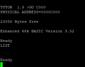
There was a commercial design that is compatible, the Motorola MC68000 Educational Computer Board (MEX68KECB) (referred to as MECB). There is a TUTOR monitor, Tiny BASIC, Enhanced BASIC, and FORTH for the board.

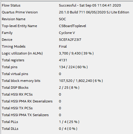
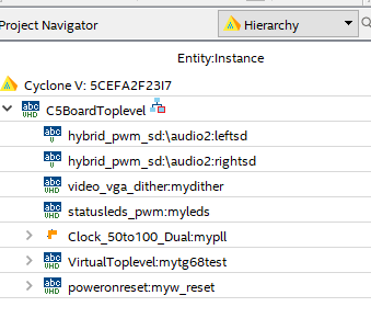
The design doesn't fit into the minimal Multicomp FPGA board due to the memory requirements. It does fit into a larger FPGA like the Altera/Intel EP4CE15. I am using my RETRO-EP4CE15 card as the hardware platform which support Cyclone IV and Cyclone V FPGAs..

The main features are:

  • M68000 CPU
  • Teesite TS2BUG (4KB) or MECB TUTOR (16KB) Monitor ROMs
  • 32KB Internal SRAM
  • ANSI Video Display Unit (VDU)
    • VGA and PS/2
  • 6850 ACIA UART
    • USB to Serial
  • SD Card
    • Supports SD or SDHC cards
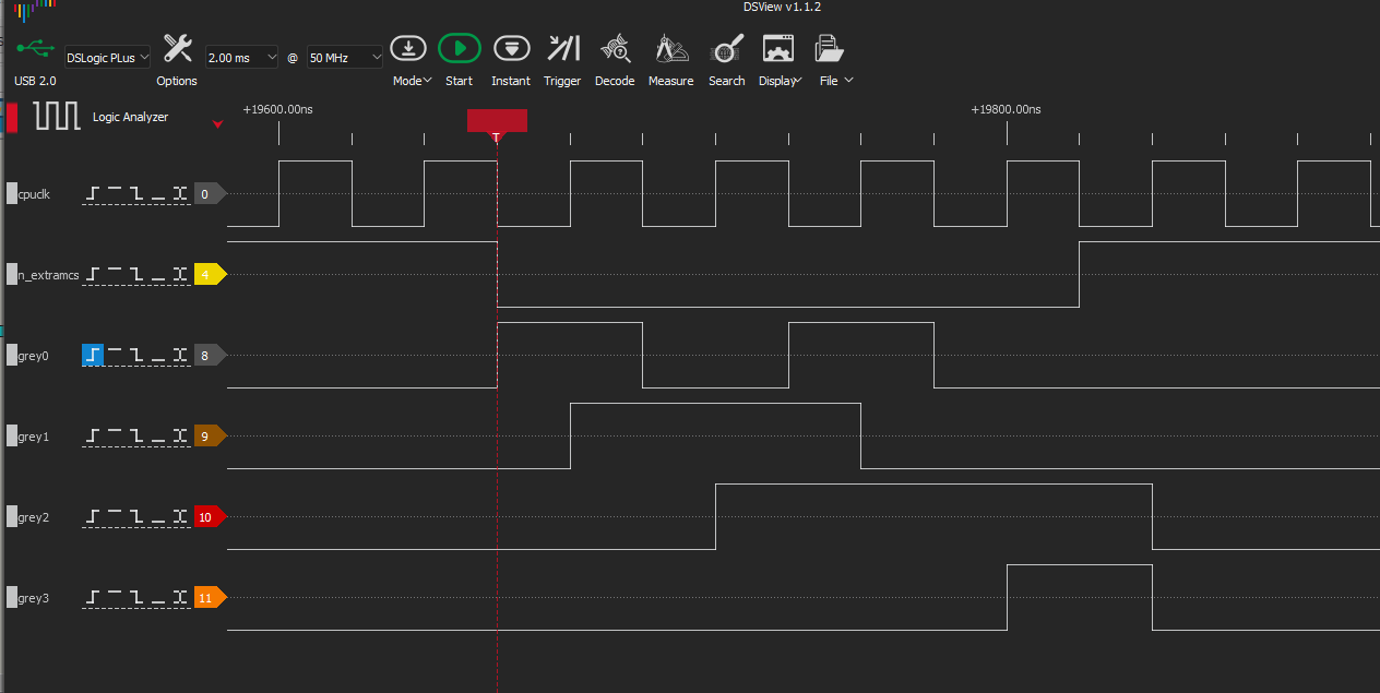
  • GPIO
    • 3 + 8 + 8 Input-Output bits
  • USB powered over USB-Serial connection

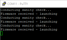
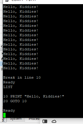
The board works and loads Gordo's MC68000 Tiny BASIC v1.2 as well as EnhBASIC.

  • Toochain Video

    land-boards.com06/23/2022 at 23:15 0 comments

    Nice video

  • External SRAM

    land-boards.com02/25/2022 at 20:53 0 comments

    The base card has 1MB of external SRAM. It requires 3 of the 50 MHz clocks which means the CPU runs at 16.7 MHz when accessing the external SRAM. 

    Other (internal) SRAM/ROM/Peripherals accesses take 2 of 50 MHz clocks which means the CPU runs at 25 MHz for these accesses.

    Tweeked the design and it runs reliably now. Created TS2_V001 branch since it is stable. Reverted the change to the ACIA receive buffer RTS handshake depth threshold.

    Features are found here.

  • Running Forth

    land-boards.com02/25/2022 at 20:27 0 comments

    Got fig-Forth running on the card!

    • Running TUTOR Monitor on the card
    • Run puTTY
    • Type LO2 to load s-record
    • Download s-records file by copy-paste into puTTY window
    • GO 3648 (COLD location)

    Docs are here.

  • GPIO - 19 Bits

    land-boards.com02/24/2022 at 13:47 0 comments

    Added GPIO ports to FPGA design.

    Features

    • Input/Output ports
    • 3 bit port
    • (2) 8 bit ports
    • Two locations from CPU
      • Register/port selection - indirect
        • Set bit direction
      • Data port
    • Connects to J2 connector

    Indirect Register

    -- 0 DAT0 bits [2:0]
    -- 1 DDR0 bits [2:0]
    -- 2 DAT2 bits [7:0]
    -- 3 DDR2 bits [7:0]
    -- 4 DAT3 bits [7:0]
    -- 5 DDR3 bits [7:0]

    Data Direction Register Bits

    -- 0 in the data direction register marks the bit as an output
    -- 1 in the data direction register marks it as an input

    After reset, GPIOADR=0, all DDR*=0 (output) all DAT*=0 (output low). 

    Route to DB-25 on MultiComp in a Box design.

  • SD Card Support

    land-boards.com02/24/2022 at 13:27 0 comments

    Added SD Card support. The SD card VHDL code comes from MultiComp.

    Memory Map

    --        0x010050-0x010058F - SD Card
    --            0x010051 - SDDATA        read/write data
    --            0x010053 - SDSTATUS    read
    --            0x010053 - SDCONTROL    write
    --            0x010055 - SDLBA0        write-only
    --            0x010057 - SDLBA1        write-only
    --            0x010059 - SDLBA2        write-only (only bits 6:0 are valid)

    C Code to Read First SD Card Block to SRAM

    // SDCard.c
    
    #define ACIASTAT    (volatile unsigned char *) 0x010041
    #define ACIADATA    (volatile unsigned char *) 0x010043
    #define VDUSTAT        (volatile unsigned char *) 0x010040
    #define VDUDATA        (volatile unsigned char *) 0x010042
    #define ACIA_TXRDYBIT 0x2
    
    // SD Card
    #define SD_SDDATA_REG    (volatile unsigned char *) 0x010051
    #define SD_STATUS_REG    (volatile unsigned char *) 0x010053
    #define SD_CMD_REG        (volatile unsigned char *) 0x010053
    #define SD_LBA0_REG        (volatile unsigned char *) 0x010055
    #define SD_LBA1_REG        (volatile unsigned char *) 0x010057
    #define SD_LBA2_REG        (volatile unsigned char *) 0x010059
    // SD Card Status Reg
    #define SD_WR_RDY        0X80
    #define SD_RD_RDY        0X40
    #define SD_BLK_BUSY        0X20
    #define SD_INIT_BUSY    0X10
    // SD Card Control values
    #define SD_RD_BLK    0x00
    #define SD_WR_BLK    0x01
    #define BUFFER_START 0XE000
    
    /*
    -- To read a 512-byte block from the SDCARD:
    -- Wait until SDSTATUS=0x80 (ensures previous cmd has completed)
    -- Write SDLBA0, SDLBA1 SDLBA2 to select block index to read from
    -- Write 0 to SDCONTROL to issue read command
    -- Loop 512 times:
    --     Wait until SDSTATUS=0xE0 (read byte ready, block busy)
    --     Read byte from SDDATA
    --
    -- To write a 512-byte block to the SDCARD:
    -- Wait until SDSTATUS=0x80 (ensures previous cmd has completed)
    -- Write SDLBA0, SDLBA1 SDLBA2 to select block index to write to
    -- Write 1 to SDCONTROL to issue write command
    -- Loop 512 times:
    --     Wait until SDSTATUS=0xA0 (block busy)
    --     Write byte to SDDATA
    */
    
    // Prototypes
    void printCharToACIA(unsigned char);
    void printStringToACIA(const char *);
    void printCharToVDU(unsigned char);
    void printStringToVDU(const char *);
    void waitUART(unsigned int waitTime);
    void wait_Until_SD_CMD_Done(void);
    void write_SD_LBA(unsigned long);
    void readSDBlockToBuffer(void);
    void wait_Until_SD_Char_RD_Rdy(void);
    
    int main(void)
    {
        asm("move.l #0x1000,%sp"); // Set up initial stack pointer
    
        printStringToVDU("Waiting on SD Card ready\n\r");
        wait_Until_SD_CMD_Done();
        printStringToVDU("SD Card is ready\n\r");
        printStringToVDU("Writing LBA = 0\n\r");
        write_SD_LBA(0);
        printStringToVDU("Reading block\n\r");
        readSDBlockToBuffer();
        printStringToVDU("Block was read to 0xE000\n\r");
        asm("move.b #228,%d7\n\t"
            "trap #14");
        return(0);
    }
    
    void readSDBlockToBuffer(void)
    {
        unsigned short loopCount = 512;
        unsigned char readSDChar;
        unsigned char * destAddr;
        destAddr = (unsigned long) BUFFER_START;
        * SD_CMD_REG = SD_RD_BLK;
        while (loopCount > 0)
        {
            wait_Until_SD_Char_RD_Rdy();
            readSDChar = *SD_SDDATA_REG;
            *destAddr++ = readSDChar;
            loopCount--;
        }
    }
    
    void write_SD_LBA(unsigned long lba)
    {
        unsigned char lba0, lba1, lba2;
        lba0 = lba & 0xff;
        lba1 = (lba >> 8) & 0xff;
        lba2 = (lba >> 16) & 0xff;
        * SD_LBA0_REG = lba0;
        * SD_LBA1_REG = lba1;
        * SD_LBA2_REG = lba2;
    }
    
    void wait_Until_SD_Char_RD_Rdy(void)
    {
        unsigned char charStat;
        charStat = * SD_STATUS_REG;
        while (charStat != 0xE0)
        {
            charStat = *SD_STATUS_REG;
        }
    }
    
    void wait_Until_SD_CMD_Done(void)
    {
        unsigned char charStat;
        charStat = * SD_STATUS_REG;
        while (charStat != 0x80)
        {
            charStat = *SD_STATUS_REG;
        }
    }
    
    void waitUART(unsigned int waitTime)
    {
        volatile unsigned int timeCount = 0;
        for (timeCount = 0; timeCount < waitTime; timeCount++);
    }
    
    void printCharToACIA(unsigned char charToPrint)
    {
        while ((*ACIASTAT & ACIA_TXRDYBIT) != ACIA_TXRDYBIT);
        * ACIADATA = charToPrint;
    }
    
    void printStringToACIA(const char * strToPrint)
    {
        int strOff = 0;
        while(strToPrint[strOff] != 0)
            printCharToACIA(strToPrint[strOff++]);
    }
    
    void printCharToVDU(unsigned char charToPrint)
    {
        while ((*VDUSTAT & ACIA_TXRDYBIT) != ACIA_TXRDYBIT);
     * VDUDATA = charToPrint;
    ...
    Read more »

  • Fixing Handshakes

    land-boards.com02/21/2022 at 12:04 0 comments

    Tried loading from the serial port and had issues again.

    Found the problem is related to the inability of the n_rts line to respond early enough to slow the USB (FPGA to Host) handshake in time. The bufferedUART.vhd code was set to turn off RTS when there are > 8 chars in the receive buffer. The FT230X part doesn't react that fast. Changing the threshold to 4 fixed the problem.

        -- RTS with hysteresis
        -- enable flow if less than 2 characters in buffer
        -- stop flow if greater that 4 chars in buffer (to allow 12 byte overflow)
        -- USB-Serial is fast, but not fast enough to make this larger
        process (clk)
        begin
            if rising_edge(clk) then
                if rxBuffCount<2 then
                    n_rts <= '0';
                end if;
                if rxBuffCount>4 then
                    n_rts <= '1';
                end if;
            end if;
        end process;
    

    I can now download code again.

    Download Code Procedure

    • Run puTTY on the Serial port
      • puTTY conflicts with the USB Blaster so it has to be shut down 
      • puTTY should be set to no add LF or CR
      • Assuming the file already has CR LF on each line
      • Can check by puTTY settings, Terminal Implicit LF or CR turned off
    • Open the download file in a text editor
      • I like notepad++
      • Make sure the last line in the file to download is
        • S9032000DC
        • If it's not, add the S9 line with a CR at the end of the line
      • Select all, copy to copy-paste buffer (CTRL-C)
    • Type LO2 on the VDU keyboard.
    • On the Serial port, insert the text with CTRL-V
    • After the download, TUTOR will return to the prompt
    • Ready to run the program
      • GO addr

  • SDRAM Working in a Different Context

    land-boards.com09/05/2020 at 12:28 0 comments

    There's an interesting project from 2014 called TG68 Experiments at Retro Ramblings (AMR) to create a 68000 CPU that uses the SDRAM on these inexpensive FPGA cards. The project starts with the 68K same core (TG68) I've been using by Tobias Gubener and builds on it. It improves on the TG68 SDRAM design considerably. Here's the GitHub repository for the project.

    This project has quite a few appealing features including a large frame buffer and the ability to load code from an SD Card. AMR has spent quite a bit of time building a fast SDRAM interface including a 2-way associative cache. He also does pixel dithering which I used to map the 16 bit graphics to the 6-bits of the RETRO-EP4CE15 card. 

    It took a solid day of fumbling around to port it to my RETRO-EP4CE15 card with a Cyclone V FPGA card but it's now running. In the end I routed some of the obvious lines (resets. clocks) out to the FPGA's extra I/O pins and used my logic analyzer and scope to debug the problems. The project is pretty well documented but the following are my notes from the port.

    Here's a picture of the screen on a VGA monitor.

    Fits in Cyclone V FPGA

    There's plenty of room on the Cyclone V FPGA. It should fit in a smaller FPGA just fine.

    Started with Cyclone III Example

    AMR chose a cheap Cyclone III card from flea bay. I chose to port the Cyclone III example thinking it might be closer to my Cyclone V FPGA card than the other board examples. That might not be the case, but it is what I did. The other boards had a lot more LEDs, switches, etc. The Cyclone III card had minimal resources.

    The card had two SDRAMs so it took some effort to remove support for the second SDRAM. In fact, that was the last domino to fall since I still had VHDL fragments from the 2nd PLL which I had only partially removed so it was causing the 68K to stay in reset.

    Serial Port Message

    On the way to booting, this status message was printed to the serial port (at 115,200 baud) (several reboots shown below):

    SD Card Contents

    AMR's TG68 Experiments needs an SD card with some specific contents, namely an S-Record file with the boot code. AMR bootstraps directly from the SD card so the bootstrap code needs to be in the root folder with a specific file name.

    If you want to try it out, just copy the file 
    CFirmware/out.srec to the root of the SD card, 
    and rename it to “boot.sre”. 

    That seems to be working since I see a window on the VGA screen with S-Records. 

    Here's one of the s-records from the VGA screen compared to the out.srec file contents. Not sure why there's less lines in the window but the one line does look right.

    I wonder if this shouldn't be different code, namely the sdbootstrap.srec file.

    I tried a few different sre files and they seemed to all work.

    Replaced the PLL with a Cyclone V PLL

    Quartus seems finicky with upgrading the PLL so I re-generated another one. The outputs are 100 MHz, 100 MHz, and 25 MHz in case someone tries to figure it out.

    How the Top Looks in Quartus

    This view of the hierarchy in Quartus might be helpful:

    Building the Code

    I copied the code to my Linux Virtual Machine (built earlier). However the code requires vasm which I don't have at the moemnt.

    My GitHub Repo

    The code for this project is in my Retro-Computers GitHub repository. The VHDL code for the build starts in here.

    End of TS2 Series?

    This could be the end of this TS2 series. I think I will shift over to getting the TG68 as implemented by AMR working.

    Postscript

    Rebuilt the EP4CE15 version of the card using the lessons learned from the Cyclone V build including the busstate signals and the External 1MB SRAM. Tested the build and it worked. Here in GitHub.

  • Built demo.c

    land-boards.com08/30/2020 at 14:12 0 comments

    Jeff Tranter has a piece of demo code that is written in C.  The code prints lines with number of 1 to 11 along with the number squared, the number to the 4th power and the factorial of the number

    Makefile Issues

    Jeff's Makefile has troubles with my version of the GCC compiler but all I needed to do to fix it was remove the include for the coff file. Doesn't seem to be a problem since obj-copy figures out the file type without it. I had the same issue with building assembly code.

    The Makefile has:

    all:    demo.run demo.s
    
    demo.run: demo.c
        /opt/m68k-elf/bin/m68k-elf-gcc -Wall -m68000 -msoft-float -c demo.c
        /opt/m68k-elf/bin/m68k-elf-ld --defsym=_start=main -Ttext=0x2000 -Tdata=0x3000 -Tbss=0x4000 --section-start=.rodata=0x5000 demo.o `/opt/m68k-elf/bin/m68k-elf-gcc -m68000 -print-libgcc-file-name`
        /opt/m68k-elf/bin/m68k-elf-objcopy -O srec a.out demo.run
    
    demo.s: demo.c
        /opt/m68k-elf/bin/m68k-elf-gcc -Wall -nostdlib -nodefaultlibs -m68000 -S demo.c
    
    clean:
        $(RM) a.out demo.o demo.run demo.s    

    Running the Program

    The program starts running at address 0x2000 and does the following:

    TUTOR  1.3 > GO 2000
    PHYSICAL ADDRESS=00002000
    Start
    n  n^2  n^4  n!
    1 1 1 1
    2 4 8 2
    3 9 27 6
    4 16 64 24
    5 25 125 120
    6 36 216 720
    7 49 343 5040
    8 64 512 40320
    9 81 729 362880
    10 100 1000 3628800
    11 121 1331 39916800
    Done
    
    TUTOR  1.3 >
    

    Useful Functions in example code

    Jeff provides two functions which use the TUTOR monitor for calls:

    void outch(const char c);
    void printString(const char *s);
    

    The code for these programs is: 

    // Print a character using the TUTOR monitor trap function.
    void outch(char c) {
        asm("movem.l %d0/%d1/%a0,-(%sp)\n\t"  // Save modified registers
            "move.b %d0,%d0\n\t"              // Put character in D0
            "move.b #248,%d7\n\t"             // OUTCH trap function code
            "trap #14\n\t"                    // Call TUTOR function
            "movem.l (%sp)+,%d0/%d1/%a0");    // Restore registers
    }
    
    // Print a string.
    void printString(const char *s) {
        while (*s != 0) {
            outch(*s);
            s++;
        }
    }
    

    The outch( ) routine is conveniently written in assembly so it provides a nice example of in-line assembly language code. 

    Return to TUTOR

    main( ) cleanly returns to the Tutor monitor. It does that by using a TRAP:

    // Go to the TUTOR monitor using trap 14 function. Does not return.
    void tutor() {
        asm("move.b #228,%d7\n\t"
            "trap #14");
    }
    

    The trap 14 handler code in TUTOR header has:

    8162                   *-------------------------------------------------------------------------
     8163                   * File TRAP14    Trap 14 handler of "TUTOR"                       06/25/82
     8164                   
     8165                   *        CALLING SEQUENCE
     8166                   *                  %D7 = XXXXXXFF   WHERE "FF" IF FUNCTION NUMBER
     8167                   *                  TRAP      #14
     8168                   
     8169                   TRAP14:
     8170 be70 48E7 4160              MOVEM.L %D1/%D7/%A1-%A2,-(%A7)
    

    This finally validates the GCC toolchain works.

  • Enhanced BASIC

    land-boards.com08/30/2020 at 12:02 0 comments

    Jeff Tranter also ran the Enhanced BASIC on his TS2 build. It loads into ROM on his card from 0xC000-0xCFFF. This card is compatible with Jeff's design (it's based on Jeff's design which is a copy of the Teeside TS2 board so any software that Jeff got running should run on this card.

    I added a 16KB internal SRAM to that range and uploaded Enhanced BASIC to the card and it worked.

    A short program...

    I could change the SRAM into ROM and have BASIC always ready to run.

  • Cleaning up a noisy counter

    land-boards.com08/29/2020 at 13:57 0 comments

    Later note - Went away from this approach...

    Using a binary counter for the wait states is not a good idea. The reason is that counters when decoded have noise when they transition. That's because they transition more than one bit at a time.

    The classical solution to this problem is to use a grey counter which only changes one bit at a time. It does count strangely when viewed as numbers but it's much easier to decode and it is glitch-free.

    Here's a 4 bit grey count:

    0000 -> 0001
    0001 -> 0011
    0011 -> 0010
    0010 -> 0110
    0110 -> 0111
    0111 -> 1111
    ...

    Here is the logic analyzer capture:

    Unfortunately the flakey S record load at 25 MHz happened again. Dropping back to 16.7 MHz fixed it again. Still haven't fixed the edge condition....

    Timing to access external SRAM.

View all 30 project logs

Enjoy this project?

Share

Discussions

Similar Projects

Does this project spark your interest?

Become a member to follow this project and never miss any updates